Noise measurement methodology, Average upstream noise measurement, Table 33 – Juniper Networks G10 CMTS User Manual
Page 99: Average noise spectrum analyzer settings, 83 noise measurement methodology
•
•
•
•
•
•
•
•
•
•
•
•
•
•
•
•
•
•
•
•
•
•
•
•
•
•
•
•
•
•
•
•
•
•
•
•
•
•
•
•
•
•
•
•
•
•
•
•
•
•
•
•
•
•
•
•
•
•
Prepare the Site
Noise Measurement Methodology
83
Noise Measurement Methodology
This section describes the methodology for conducting average and peak upstream noise
measurements. The procedures establish a consistent methodology for obtaining the
requested information during the characterization of the installation site. We recommend you
use the HP 8591C spectrum analyzer for taking these measurements.
Average Upstream Noise Measurement
This section defines a procedure for taking the average upstream noise measurements
required as part of the RF plant and HFC environment characterization. We recommend that
you take a sample of 10 percent of the nodes terminated at the installation site. Table 33
provides the appropriate setup configuration settings for the HP 8591C spectrum analyzer.
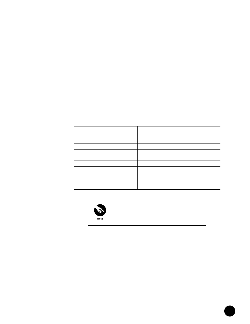
Table 33: Average Noise Spectrum Analyzer Settings
1.
Connect the spectrum analyzer to the selected upstream signal at the upstream splitter
or at the CMTS upstream port.
2.
Configure the spectrum analyzer using the values defined in Table 33.
3.
Start the measurement.
After completing the measurement, the analyzer display should resemble Figure 23 on
page 84.
Setting
Value
Start frequency
2 MHz
Stop frequency
45 MHz
Resolution bandwidth
100 kHz
Video bandwidth
30 kHz
Scale
5 dB/div
Internal amplifier
On
Attenuator
0 dB
Reference level offset
-28 dB
Reference level
-5 dBmV
Number of averages
100
You might need to adjust the reference level for your
particular test environment.