Figure 6, Rear view of fully configured chassis, G10 cmts hardware overview – Juniper Networks G10 CMTS User Manual
Page 29: Figure 6: rear view of fully configured chassis, System overview
•
•
•
•
•
•
•
•
•
•
•
•
•
•
•
•
•
•
•
•
•
•
•
•
•
•
•
•
•
•
•
•
•
•
•
•
•
•
•
•
•
•
•
•
•
•
•
•
•
•
•
•
•
•
•
•
•
•
System Overview
G10 CMTS Hardware Overview
13
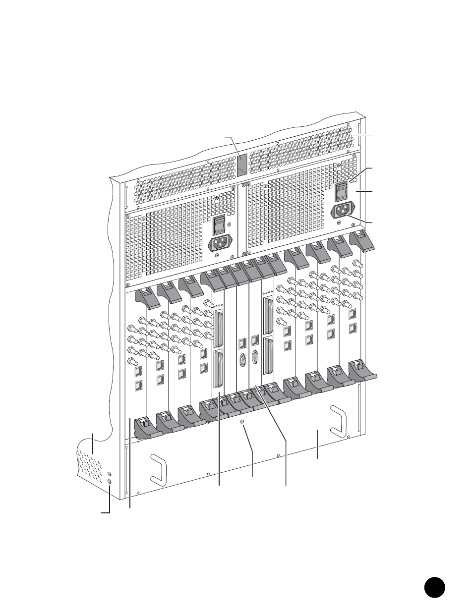
Figure 6: Rear View of Fully Configured Chassis
Eth0
Eth1
US 3
US 2
US 1
US 0
DS 3
DS 2
DS 1
DS 0
Eth0
Eth1
US 3
US 2
US 1
US 0
DS 3
DS 2
DS 1
DS 0
Eth0
Eth1
US 3
US 2
US 1
US 0
DS 3
DS 2
DS 1
DS 0
Eth0
Eth1
US 3
US 2
US 1
US 0
DS 3
DS 2
DS 1
DS 0
EXT F
A
UL
T
INT F
A
UL
T
OPERA
TIONAL
PO
WER
EXT F
A
UL
T
INT F
A
UL
T
OPERA
TIONAL
PO
WER
US 3
US 2
US 1
US 0
DS 3
DS 2
DS 1
DS 0
Eth1
Eth0
Eth1
US 3
US 2
US 1
US 0
DS 3
DS 2
DS 1
DS 0
Eth1
US 3
US 2
US 1
US 0
DS 3
DS 2
DS 1
DS 0
Eth0
Eth0
1
2
Eth1
US 3
US 2
US 1
US
DS 3
DS 2
DS 1
DS 0
Eth0
0
1
2
1
2
Eth
C
O
M
Eth
C
O
M
Rear Fan
Tray
Cable
Channel
AC Power
Receptacle
AC Power
Transition
Module
AC Power
Switch
Air
Exhaust
Rear Fan
Tray LED
Chassis
Ground
Nuts
Air
Intake
HFC
Connector
Module
CCM
Access
Module
NIC
Access
Module