Figure 4, Front view of fully configured chassis, G10 cmts hardware overview – Juniper Networks G10 CMTS User Manual
Page 27: Figure 4: front view of fully configured chassis, Front fan tray led esd strap jack air intake
•
•
•
•
•
•
•
•
•
•
•
•
•
•
•
•
•
•
•
•
•
•
•
•
•
•
•
•
•
•
•
•
•
•
•
•
•
•
•
•
•
•
•
•
•
•
•
•
•
•
•
•
•
•
•
•
•
•
System Overview
G10 CMTS Hardware Overview
11
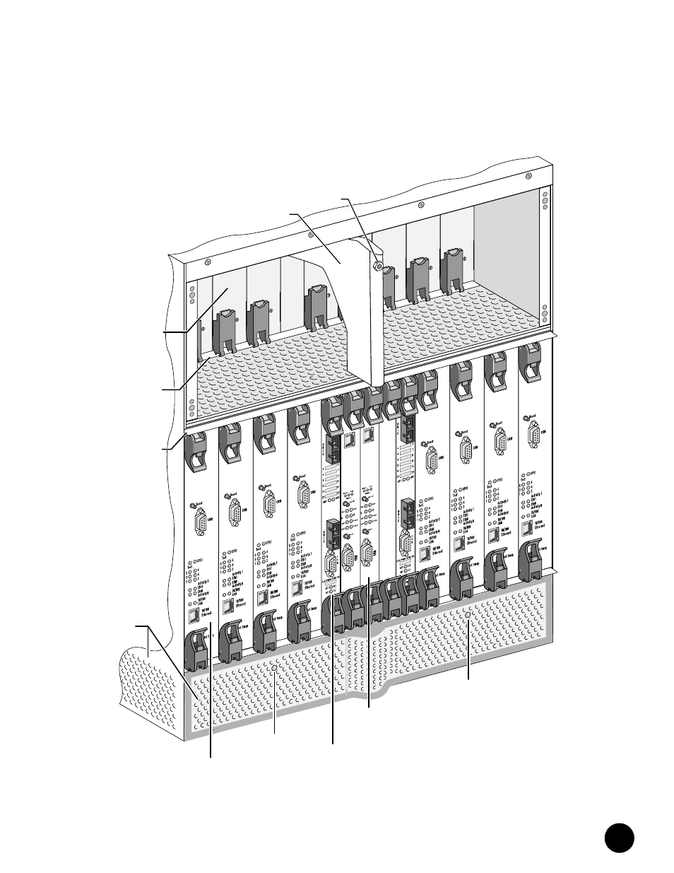
Figure 4: Front View of Fully Configured Chassis
Power
Fault
Power
Fault
Power
Fault
Power
Fault
Power
Fault
Power
Fault
Power
Fault
Power
Fault
Front Fan
Tray LED
ESD
Strap
Jack
Air
Intake
Eth0
1
2
Eth0
1
2
Front Fan
Tray LED
DOCSIS
Module
NIC
Module
Chassis
Control
Module
Cable
Guide
Power
Supply
Power
Supply
Ejector
Rail
Module
Ejector
Rail