Figure 44: power supply removal – Juniper Networks G10 CMTS User Manual
Page 177
•
•
•
•
•
•
•
•
•
•
•
•
•
•
•
•
•
•
•
•
•
•
•
•
•
•
•
•
•
•
•
•
•
•
•
•
•
•
•
•
•
•
•
•
•
•
•
•
•
•
•
•
•
•
•
•
•
•
Replacement Procedures
Power Supplies
161
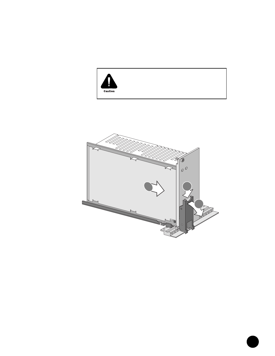
6.
Replace the power supply faceplate by aligning its four ball studs with the four power
supply faceplate clips and pressing the faceplate towards the chassis until it snaps into
place.
See “Install Power Supplies” on page 101 for power supply installation instructions.
Figure 44: Power Supply Removal
The power supply faceplate and power supply filler panels
must be installed before you power on the G10 CMTS to
ensure that proper air ventilation occurs throughout the
chassis, and to reduce EMI emissions.
3
2
1