Derating curves, Reset – Intel 80L186EA User Manual
Page 33
80C186EA 80C188EA 80L186EA 80L188EA
DERATING CURVES
272432 – 13
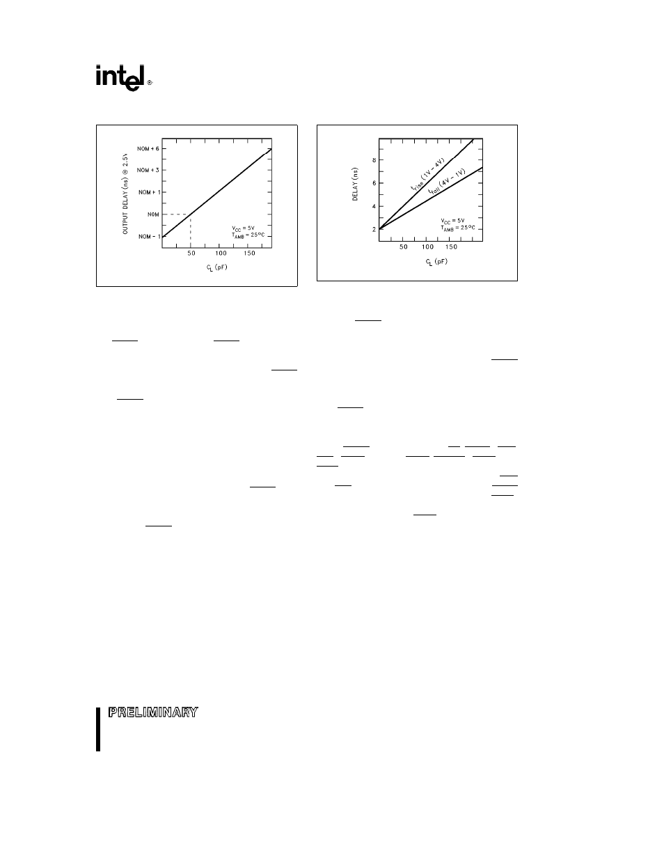
Figure 13 Typical Output Delay Variations
Versus Load Capacitance
272432 – 14
Figure 14 Typical Rise and Fall Variations
Versus Load Capacitance
RESET
The processor performs a reset operation any time
the RESIN pin is active The RESIN pin is actually
synchronized before it is presented internally which
means that the clock must be operating before a
reset can take effect From a power-on state RESIN
must be held active (low) in order to guarantee cor-
rect initialization of the processor Failure to pro-
vide RESIN while the device is powering up will
result in unspecified operation of the device
Figure 15 shows the correct reset sequence when
first applying power to the processor An external
clock connected to CLKIN must not exceed the V
CC
threshold being applied to the processor This is nor-
mally not a problem if the clock driver is supplied
with the same V
CC
that supplies the processor
When attaching a crystal to the device RESIN must
remain active until both V
CC
and CLKOUT are stable
(the length of time is application specific and de-
pends on the startup characteristics of the crystal
circuit) The RESIN pin is designed to operate cor-
rectly using an RC reset circuit but the designer
must ensure that the ramp time for V
CC
is not so
long that RESIN is never really sampled at a logic
low level when V
CC
reaches minimum operating
conditions
Figure 16 shows the timing sequence when RESIN
is applied after V
CC
is stable and the device has
been operating Note that a reset will terminate all
activity and return the processor to a known operat-
ing state Any bus operation that is in progress at the
time RESIN is asserted will terminate immediately
(note that most control signals will be driven to their
inactive state first before floating)
While RESIN is active signals RD QSMD UCS
LCS MCS0 PEREQ MCS1 ERROR LOCK and
TEST BUSY are configured as inputs and weakly
held high by internal pullup transistors Forcing UCS
and LCS low selects ONCE Mode Forcing QSMD
low selects Queue Status Mode Forcing TEST
BUSY high at reset and low four clocks later enables
Numerics Mode Forcing LOCK low is prohibited and
results in unspecified operation
33
33