Ac specifications – Intel 80L186EA User Manual
Page 26
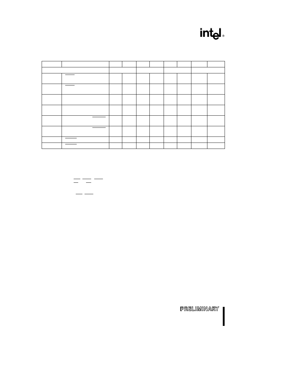
80C186EA 80C188EA 80L186EA 80L188EA
AC SPECIFICATIONS
(Continued)
AC Characteristics
80C186EA25 80C186EA20 80C186EA13
Symbol
Parameter
Min
Max
Min
Max
Min
Max
Units
Notes
SYNCHRONOUS INPUTS
25 MHz
(12)
20 MHz
13 MHz
T
CHIS
TEST NMI INT3 0
8
10
10
ns
1 9
T1 0IN ARDY
T
CHIH
TEST NMI INT3 0
3
3
3
ns
1 9
T1 0IN ARDY
T
CLIS
AD15 0 (AD7 0) ARDY
10
10
10
ns
1 10
SRDY DRQ1 0
T
CLIH
AD15 0 (AD7 0) ARDY
3
3
3
ns
1 10
SRDY DRQ1 0
T
CLIS
HOLD PEREQ ERROR
10
10
10
ns
1 9
(80C186EA Only)
T
CLIH
HOLD PEREQ ERROR
3
3
3
ns
1 9
(80C186EA Only)
T
CLIS
RESIN (to CLKIN)
10
10
10
ns
1 9
T
CLIH
RESIN (from CLKIN)
3
3
3
ns
1 9
NOTES
1 See AC Timing Waveforms for waveforms and definition
2 Measured at V
IH
for high time V
IL
for low time
3 Only required to guarantee I
CC
Maximum limits are bounded by T
C
T
CH
and T
CL
4 Specified for a 50 pF load see Figure 13 for capacitive derating information
5 Specified for a 50 pF load see Figure 14 for rise and fall times outside 50 pF
6 See Figure 14 for rise and fall times
7 T
CHOV1
applies to BHE (RFSH) LOCK and A19 16 only after a HOLD release
8 T
CHOV2
applies to RD and WR only after a HOLD release
9 Setup and Hold are required to guarantee recognition
10 Setup and Hold are required for proper operation
11 T
CHOVS
applies to BHE (RFSH) and A19 16 only after a HOLD release
12 Operating conditions for 25 MHz are 0 C to a70 C V
CC
e
5 0V
g
10%
Pin names in parentheses apply to the 80C188EA 80L188EA
26
26