Intel 80L186EA User Manual
Page 14
80C186EA 80C188EA 80L186EA 80L188EA
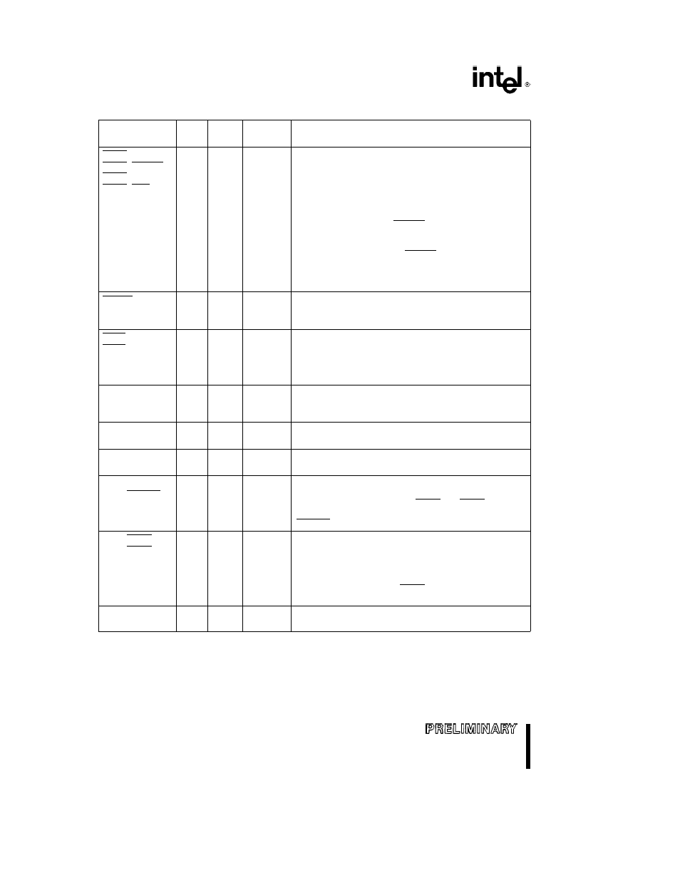
Table 3 Pin Descriptions
(Continued)
Pin
Pin
Input
Output
Description
Name
Type
Type
States
MCS0 PEREQ
I O
A(L)
H(1)
These pins provide a multiplexed function If enabled
these pins normally comprise a block of Mid-Range Chip
MCS1 ERROR
R(1)
Select
outputs which will go active whenever the address
MCS2
P(1)
of a memory bus cycle is within the address limitations
MCS3 NCS
programmed by the user In Numerics Mode (80C186EA
only) three of the pins become handshaking pins for the
80C187 The CoProcessor REQuest input signals that a
data transfer is pending ERROR is an input which
indicates that the previous numerics coprocessor
operation resulted in an exception condition An interrupt
Type 16 is generated when ERROR is sampled active at
the beginning of a numerics operation Numerics
Coprocessor Select
is an output signal generated when
the processor accesses the 80C187
PCS4 0
O
H(1)
Peripheral Chip Selects
go active whenever the address
of a memory or I O bus cycle is within the address
R(1)
limitations programmed by the user
P(1)
PCS5 A1
O
H(1) H(X)
These pins provide a multiplexed function As additional
Peripheral Chip Selects
they go active whenever the
PCS6 A2
R(1)
address of a memory or I O bus cycle is within the
P(1)
address limitations by the user They may also be
programmed to provide latched Address A2 1 signals
T0OUT
O
H(Q)
Timer OUTput
pins can be programmed to provide a
single clock or continuous waveform generation
T1OUT
R(1)
depending on the timer mode selected
P(Q)
T0IN
I
A(L)
Timer INput
is used either as clock or control signals
depending on the timer mode selected
T1IN
A(E)
DRQ0
I
A(L)
DMA ReQuest
is asserted by an external request when it
is prepared for a DMA transfer
DRQ1
INT0
I
A(E L)
Maskable INTerrupt input will cause a vector to a specific
Type interrupt routine To allow interrupt expansion INT0
INT1 SELECT
and or INT1 can be used with INTA0 and INTA1 to
interface with an external slave controller INT1 becomes
SELECT when the ICU is configured for Slave Mode
INT2 INTA0
I O
A(E L)
H(1)
These pins provide multiplexed functions As inputs they
provide a maskable INTerrupt that will cause the CPU to
INT3 INTA1 IRQ
R(Z)
vector to a specific Type interrupt routine As outputs
P(1)
each is programmatically controlled to provide an
INTerrupt Acknowledge
handshake signal to allow
interrupt expansion INT3 INTA1 becomes IRQ when the
ICU is configured for Slave Mode
N C
No Connect
For compatibility with future products do not
connect to these pins
NOTE
Pin names in parentheses apply to the 80C188EA and 80L188EA
14
14