Figure 101. typical dma transfer – Intel 80C188XL User Manual
Page 257
DIRECT MEMORY ACCESS UNIT
10-2
When the DMA request is granted, the Bus Interface Unit provides the bus signals for the DMA
transfer, while the DMA channel provides the address information for the source and destination
devices. The DMA Unit does not provide a discrete DMA acknowledge signal, unlike other DMA
controller chips (an acknowledge can be synthesized, however). The DMA channel continues
transferring data as long as the request is active and it has not exceeded its programmed transfer
limit.
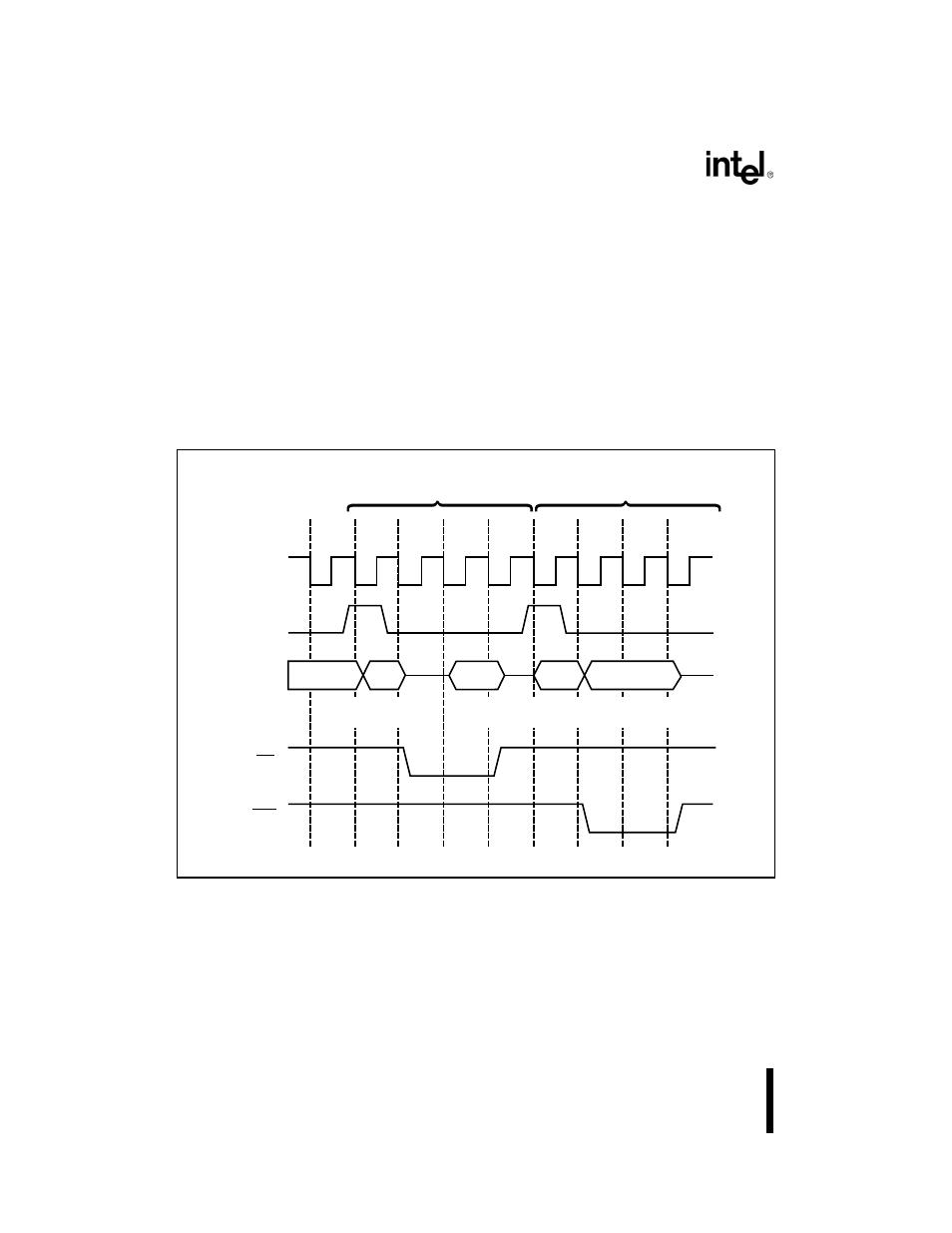
Every DMA transfer consists of two distinct bus cycles: a fetch and a deposit (see Figure 10-1 on
page 10-2). During the fetch cycle, the byte or word is read from the data source and placed in an
internal temporary storage register. The data in the temporary storage register is written to the
destination during the deposit cycle. The two bus cycles are indivisible; they cannot be separated
by a bus hold request, a refresh request or another DMA request.
Figure 10-1. Typical DMA Transfer
TI
T1
T2
T3
CLKOUT
ALE
T4
T1
T2
T3
T4
WR
RD
AD15:0
Source
Address
Destination
Data
Destination
Address
Source
Data
Fetch
Deposit
A1186-0A