Figure 36. typical bus cycle, Figure 37. t-state relation to clkout – Intel 80C188XL User Manual
Page 89
BUS INTERFACE UNIT
3-8
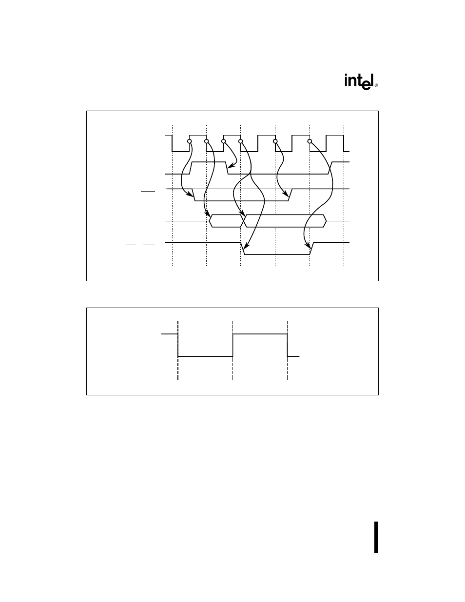
Figure 3-6. Typical Bus Cycle
Figure 3-7. T-State Relation to CLKOUT
Figure 3-8 shows the BIU state diagram. Typically a bus cycle consists of four consecutive T-
states labeled T1, T2, T3 and T4. A TI (idle) state occurs when no bus cycle is pending. Multiple
T3 states occur to generate wait states. The TW symbol represents a wait state.
The operation of a bus cycle can be separated into two phases:
•
Address/Status Phase
•
Data Phase
CLKOUT
RD / WR
Valid Status
ALE
AD15:0
S2:0
T4
T1
T2
T3
T4
Data
Address
A1507-0A
CLKOUT
(Low Phase)
(High Phase)
Phase 1
Phase 2
TN
Falling
Edge
Rising
Edge
A1111-0A
This manual is related to the following products: