Figure 105. two-channel dma module – Intel 80C188XL User Manual
Page 264
10-9
DIRECT MEMORY ACCESS UNIT
The last point is extremely important when the two channels use different synchronization. For
example, consider the case in which channel 1 is programmed for high priority and destination
synchronization and channel 0 is programmed for low priority and source synchronization. If a
DMA request occurs for both channels simultaneously, channel 1 performs the first transfer. At
the end of channel 1’s deposit cycle, two idle states are inserted (thus releasing the bus). With the
bus released, channel 0 is free to perform its transfer even though the higher-priority channel
has not completed all of its transfers. Channel 1 regains the bus at the end of channel 0’s trans-
fer. The transfers will alternate as long as both requests remain active.
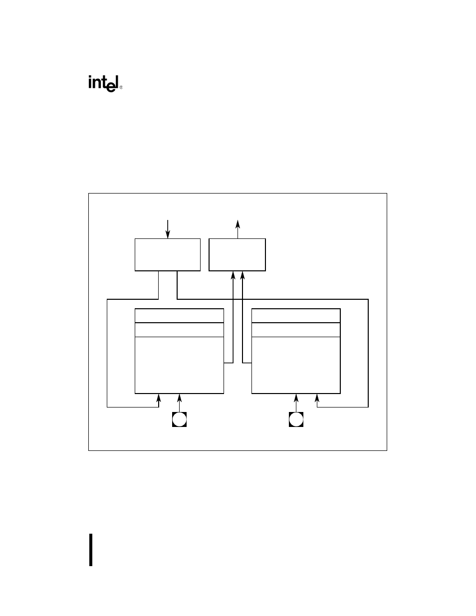
Figure 10-5. Two-Channel DMA Module
A higher-priority DMA channel will interrupt the transfers of a lower-priority channel. Figure
10-6 shows several transfers with different combinations of channel priority and synchronization.
Internal - DMA
Request
Multiplexer
Inter-module
Arbitration
Logic
Channel 1
Control Logic
DRQ Pin
DRQ Pin
Channel 0
Control Logic
Destination Pointer
Source Pointer
Destination Pointer
Source Pointer
Module
DMA Request
Timer 2
Timer 2
Request
Timer 2 Request
A1540-01