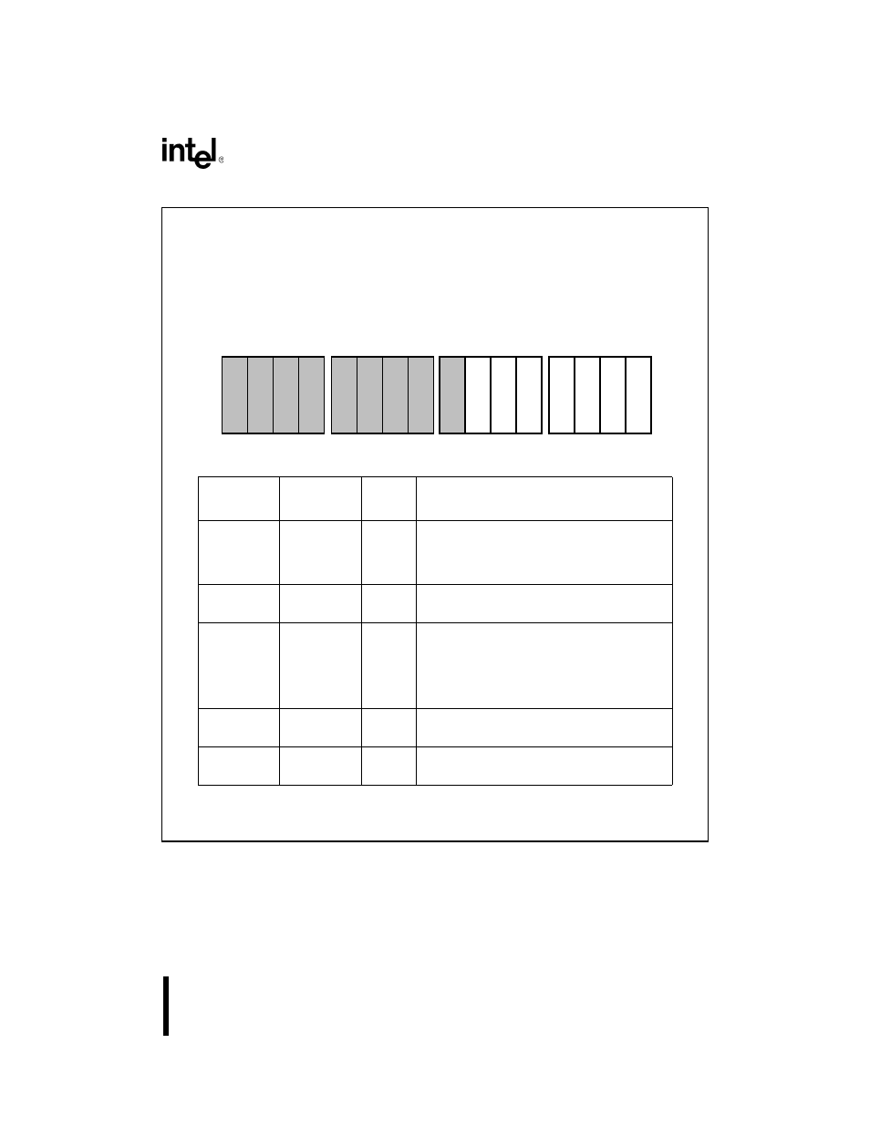
Figure 86. interrupt control register for cascada, Figure 8-6 – Intel 80C188XL User Manual
Page 210
8-15
INTERRUPT CONTROL UNIT
Figure 8-6. Interrupt Control Register for Cascadable Interrupt Pins
Register Name:
Interrupt Control Register (cascadable pins)
Register Mnemonic:
I0CON, I1CON
Register Function:
Control register for the cascadable external
interrupt pins
Bit
Mnemonic
Bit Name
Reset
State
Function
SFNM
Special
Fully
Nested
Mode
0
Set to enable special fully nested mode.
CAS
Cascade
Mode
0
Set to enable cascade mode.
LVL
Level-trigger
0
Selects the interrupt triggering mode:
0 = edge triggering
1 = level triggering.
The LVL bit
must be set
when external 8259As
are cascaded into the Interrupt Control Unit.
MSK
Interrupt
Mask
1
Clear to enable interrupts from this source.
PM2:0
Priority
Level
111
Defines the priority level for this source.
NOTE:
Reserved register bits are shown with gray shading. Reserved bits must be written
to a logic zero to ensure compatibility with future Intel products.
A1215-A0
15
0
P
M
0
P
M
1
P
M
2
M
S
K
L
V
L
C
A
S
S
F
N
M