Table d2. instruction set summary (continued), In table d-2 – Intel 80C188XL User Manual
Page 375
INSTRUCTION SET OPCODES AND CLOCK CYCLES
D-2
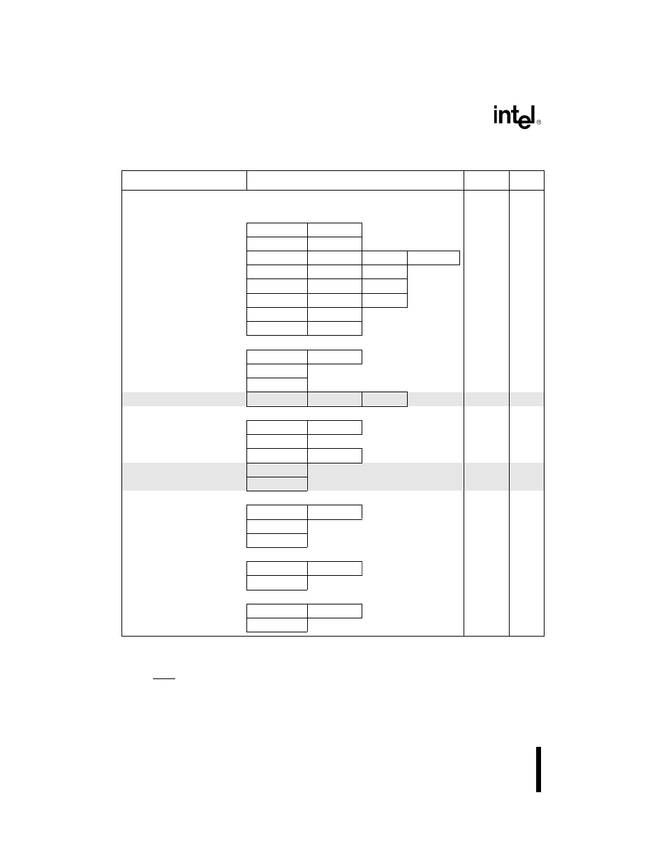
Table D-2. Instruction Set Summary
Function
Format
Clocks
Notes
DATA TRANSFER INSTRUCTIONS
MOV = Move
register to register/memory
1 0 0 0 1 0 0 w
mod reg r/m
2/12
register/memory to register
1 0 0 0 1 0 1 w
mod reg r/m
2/9
immediate to register/memory
1 1 0 0 0 1 1 w
mod 000 r/m
data
data if w=1
12/13
(1)
immediate to register
1 0 1 1 w reg
data
data if w=1
3/4
(1)
memory to accumulator
1 0 1 0 0 0 0 w
addr-low
addr-high
9
accumulator to memory
1 0 1 0 0 0 1 w
addr-low
addr-high
8
register/memory to segment register
1 0 0 0 1 1 1 0
mod 0 reg r/m
2/9
segment register to register/memory
1 0 0 0 1 1 0 0
mod 0 reg r/m
2/11
PUSH = Push
memory
1 1 1 1 1 1 1 1
mod 110 r/m
16
register
0 1 0 1 0 reg
10
segment register
0 0 0 reg 1 1 0
9
immediate
0 1 1 0 1 0 s 0
data
data if s=0
10
POP = Pop
memory
1 0 0 0 1 1 1 1
mod 000 r/m
20
register
0 1 0 1 1 reg
10
segment register
0 0 0 reg 1 1 1
(reg ?01)
8
PUSHA = Push all
0 1 1 0 0 0 0 0
36
POPA = Pop all
0 1 1 0 0 0 0 1
51
XCHG = Exchange
register/memory with register
1 0 0 0 0 1 1 w
mod reg r/m
4/17
register with accumulator
1 0 0 1 0 reg
3
XLAT = Translate byte to AL
1 1 0 1 0 1 1 1
11
IN = Input from
fixed port
1 1 1 0 0 1 0 w
port
10
variable port
1 1 1 0 1 1 0 w
8
OUT = Output from
fixed port
1 1 1 0 0 1 0 w
port
9
variable port
1 1 1 0 1 1 0 w
7
NOTES:
1.
Clock cycles are given for 8-bit/16-bit operations.
2.
Clock cycles are given for jump not taken/jump taken.
3.
Clock cycles are given for interrupt taken/interrupt not taken.
4.
If TEST = 0
Shading indicates additions and enhancements to the 8086/8088 instruction set. See Appendix A, “80C186
Instruction Set Additions and Extensions,” for details.