Figure 5.17, Figure 5.17) – Invacare Top End X-Terminator QR User Manual
Page 53
SECTION 5—WHEELS
53
Everyday and Sport Series Wheelchairs
10. Reposition the camber inserts to the highest degree of camber. Refer to Adjusting Rear
11. Repeat STEP 3.
12. Close the left camber clamp. Refer to Opening/Closing Camber Clamps on page 39.
13. Rotate the right toe adjustment ring until the tab stops against the upper metal tab on
the camber clamp.
14. Securely tighten set screw on right toe adjustment ring.
15. Repeat STEP 7.
16. Perform one of the following:
• Toe In/Toe Out Measurement is Within ±1/8‐inch ‐
i. Proceed to STEP 17.
• Toe In/Toe Out Measurement is Not Within ±1/8‐inch ‐
i. Repeat STEP 1.
ii. Loosen the set screw on the right toe adjustment ring.
iii. Repeat STEP 3.
iv. Repeat STEPS 12‐16 until toe in/toe out measurement is within ±1/8 inch.
17. If desired, reposition camber inserts to the desired degree of camber. Refer to
Adjusting Rear Wheel Camber on page 41.
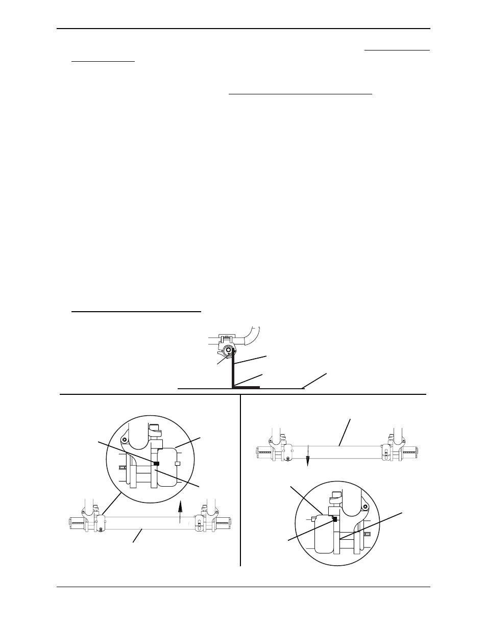
FIGURE 5.17 Adjusting the Axle Tube - A4 Camber System
Camber
Clamp
Higher Degree of Camber
Axle Tube - Will Rotate Down only
Ground/Floor
90° Angle
Place “L” Square Here
Flat Edge of
Camber Tube
Lower Degree of Camber
Right Tab
Stopped
Against
Upper Edge
of Camber
Clamp
Right Toe Adjustment
Ring
Left Tab
Stopped
Against
Lower Edge
of Camber
Clamp
Left Toe
Adjustment
Ring
Camber
Clamp
Axle Tube - Will
Rotate Up only