Camber tube 2000, A4 camber system – Invacare Top End X-Terminator QR User Manual
Page 52
SECTION 5—WHEELS
Everyday and Sport Series Wheelchairs
52
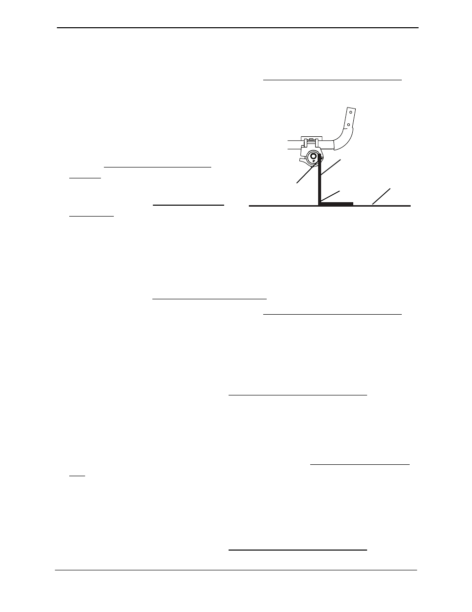
Camber Tube 2000
NOTE: For this procedure, refer to FIGURE 5.16.
1. If necessary, open both camber clamps. Refer to Opening/Closing Camber Clamps on
2. Using an ʺLʺ square, rotate the axle
tube until the flat edge of the camber
tube is at a 90° angle with the
ground/floor as shown in FIGURE 5.16.
3. Close both camber clamps. Refer to
Refer to Opening/Closing Camber
Clamps on page 39.
4. Determine the toe in/toe out of the
wheelchair. Refer to Determining Toe
In/Toe Out on page 42.
FIGURE 5.16 Adjusting the Axle Tube -
A4 Camber System
NOTE: For this procedure, refer to FIGURE 5.17.
NOTE: Before performing this procedure, make sure the camber inserts are positioned to the lowest
degree of camber. Refer to Adjusting Rear Wheel Camber on page 41.
1. If necessary, open both camber clamps. Refer to Opening/Closing Camber Clamps on
2. Loosen the set screw that secures each toe adjustment ring to the axle tube
3. Using an ʺLʺ square, rotate the axle tube until the flat edge of the camber insert is at a
90° angle with the ground/floor as shown in FIGURE 5.17.
4. Close the right camber clamp. Refer to Opening/Closing Camber Clamps on page 39.
5. Rotate the Left toe adjustment ring until the tab stops against the Lower metal tab on
the camber clamp.
6. Securely tighten set screw on left toe adjustment ring.
7. Measure the distance between the center lines at the rear and front of the rear wheels
at approximately 12 inches from the ground/floor. Refer to Determining Toe In/Toe
Out on page 42.
8. Perform one of the following:
• Toe In/Toe Out Measurement is Within ±1/8‐inch ‐ Proceed to STEP 9.
• Toe In/Toe Out Measurement is Not Within ±1/8‐inch ‐ Repeat STEPS 1‐7 until toe
in/toe out measurement is within ±1/8 inch.
9. Open the right camber clamp. Refer to Opening/Closing Camber Clamps on page 39.
Ground/
Floor
90° Angle
Place “L” Square Here
Flat Edge of
Camber Tube