Milwaukee LSM40MP-2 User Manual
Page 8
8
NOTE:.DIAGRAMS.&.ILLUSTRATIONS.ARE.NOT.TO.SCALE.
*Note: 3 in. (75 mm) above any horizontal/inclined vent component.
**Note: See Page 9, Step 1 for clearance requirements to the nailing
flange located at each side of the unit and any screw heads adjacent
to it.
The.appliance.should.be.mounted.on.a.fully.supported.base.extending.
the.full.width.and.depth.of.the.unit..The.appliance.may.be.located.on.
or. near. conventional. construction. materials.. However,. if. installed. on.
combustible.materials,.such.as.carpeting,.vinyl.tile,.etc.,.a.metal.or.wood.
barrier.covering.the.entire.bottom.surface.must.be.used.
Shelf Height
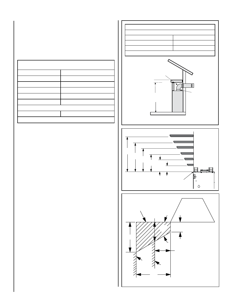
To.provide.for.the.lowest.possible.shelf.surface,.the.venting.attached.to.
the.top.vent.should.be.routed.in.a.way.to.minimize.obstructions.to.the.
space.above.the.appliance...Do.not.insulate.the.space.between.the.ap-
pliance.and.the.area.above.it.(see.
Figure 8)..The.minimum.height.from.
the.base.of.the.appliance.to.the.underside.of.combustible.materials.used.
to.construct.a.utility.shelf.in.this.fashion.is.shown.in.
Figure 8.
Wall Finishes / Surrounds / Mantels
Note: Combustible wall finish materials and/or surround materials must
not be allowed to encroach the area defined by the appliance front face
(black sheet metal). Never allow combustible materials to be positioned
in front of or overlapping the appliance face. See Figure 10 and Figure
53 on Page 28.
Non-combustible.materials,.such.as.surrounds.and.other.appliance.trim,.
may.be.installed.on.the.appliance.front.face.with.these.exceptions:.they.
must.not.cover.any.portion.of.the.removable.glass.panel.
Vertical.installation.clearances.to.combustible.mantels.vary.according.
to.the.depth.of.the.mantel...See.
Figure 9..Mantels.constructed.of.non-
combustible.materials.may.be.installed.at.any.height.above.the.appliance.
opening.
NOTE: We recommend the use of high temperature paint (rated 175° F
or higher) on the underside of the mantel.
MINIMUM CLEARANCES TO COMBUSTIBLES
The.appliance.is.approved.with.zero.clearance.to.combustible.materials.on.
all.sides.(as.detailed.in.
Table 5),.with.the.following.exception:.When the
unit is installed with one side flush with a wall, the wall on the other
side of the unit must not extend beyond the front edge of the unit..In.
addition,.when.the.unit.is.recessed,.the.side.walls.surrounding.the.unit.
must.not.extend.beyond.the.front.edge.of.the.unit.(see.
Figure 3).
Figure 10
17"
14"
8-1/4”
45°
12"
5"
12 (305)
10 (254)
8 (203)
6 (152)
4 (102)
7
(178)
17
(432)
15
(381)
13
(330)
2 (51)
9
(229)
11
(279)
Figure 9
Combustible Materials
Allowed In Shaded Area
"Safe Zone"
Top View of
Fireplace
Minimum Distance to
Protected Side Wall
Minimum Distance to
Unprotected Side Wall
Side
Wall
Side
Wall
MANTEL
CLEARANCES
Inches (mm)
Top of Appliance
MANTEL
MANTEL
MANTEL
MANTEL
MANTEL
MANTEL
Fireplace
(side view)
Figure 8
APPLIANCE MINIMUM CLEARANCES*
Inches (millimeters)
Sides
1/2 (13), 0 (0) Spacers **
Top Spacers
0 (0)
Floor
0 (0)
Back
1/2 (13), 0 (0) Spacers
Bottom of Appliance To Ceiling
69 (1743)
Vent
3 (76)
Top
* / 1 (25.4)
Sides & Bottom
SERVICE CLEARANCES
Feet (meters)
Front
3 feet (0.9 meters)
Table 5
Combustible Shelf Height -
Inches (millimeters)
Top Vent - with 2 Feet Vertical Vent and One 90 Degree Elbow
Model
Secure Vent
LSM40-2
*84-1/16 (2135)
LSM45-2
89-1/16 (2252)
* Includes 3” clearance to combustibles (required above vent components)
Do not insulate the
space between the
appliance and the
area above it.
2 Foot Vertical
Vent (Min.)
Shelf Height
(see table)
Shelf Above Fireplace With Top Venting