Milwaukee LSM40MP-2 User Manual
Page 15
NOTE:.DIAGRAMS.&.ILLUSTRATIONS.ARE.NOT.TO.SCALE.
15
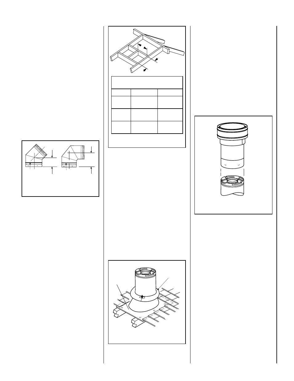
Framing Dimensions for Roof
Inches (millimeters)
Pitch
C
D
0/12
13 in.
(330 mm)
13 in.
(330 mm)
6/12
13 in.
(330 mm)
15-1/2 in.
(394 mm)
12/12
13 in.
(330 mm)
20-1/2 in.
(541 mm)
C
D
Figure 22 - Roof Framing
Figure 24
G..Continue installation of horizontal/inclined
sections -.Continue.with.the.installation.of.the.
straight.vent.sections.in.horizontal/inclined.run.
as.described.in.Step C..Install.support.straps.
every. 3'. (914. mm). along. horizontal/inclined.
vent.runs.using.conventional.plumber’s.tape..
See Page 17, Figure 28..It is very important
that the horizontal/inclined run be maintained
in a straight (no dips) and recommend to be in
a slightly elevated plane, in a direction away
from the fireplace 1/4" per foot (20 mm per
meter) which is ideal,.through.rise.per.foot.run.
ratios.that.are.smaller.are.acceptable.all.the.way.
down.to.at.or.near.level...Use.a.carpenter’s.level.
to.measure.from.a.constant.surface.and.adjust.
the.support.straps.as.necessary..
It is important to maintain the required clear-
ances to combustibles: 1" (25 mm) at all sides
for all vertical runs; and 3" (76 mm) at the top,
1" (25 mm) at sides, and 1" (25 mm) at the
bottom for all horizontal/inclined runs.
H..Frame roof opening -.Identify.location.for.
vent.at.the.roof..Cut.and/or.frame.opening.per.
Roof.Framing.Chart.(Figure 22)...
One.method.of.support.is.by.utilizing.field.pro-
vided.support.straps.(conventional.plumber's.
tape)..Secure.the.plumber's.tape.to.the.framing.
members.with.nails.or.screws. Strap.the.tape.
around.the.vent,.securing.the.ends.of.the.tape.
to.the.framing..If.desired,.sheet.metal.screws.#6.
x.1/2".length.may.be.used.to.secure.the.support.
straps.to.the.vent.pipe...See.Figure 20.
F. Change vent direction to horizontal/inclined
run -.At.transition.from.or.to.a.horizontal/inclined.
run,.install.the.SV8.E45.and.SV8.E90.elbows.in.
the.same.manner.as.the.straight.vent.sections...
The.elbows.feature.a.twist.section.to.allow.them.
to.be.routed.about.the.center.axis.of.their.initial.
collar.section.to.align.with.the.required.direc-
tion.of.the.next.vent.run.element..Twist elbow
sections in a clockwise direction only so as
to avoid the possibility of unlocking any of
the previously connected vent sections..See.
Figure 19 on Page 14 and Figure 21.
Figure 21
If.the.vent.system.extends.more.than.5.feet.(1.5.
m).above.the.roof.flashing,.stabilizers.may.be.
necessary..Additional.screws.may.be.used.at.
section.joints.for.added.stability..Guide.wires.
may.be.attached.to.the.joint.for.additional.sup-
port.on.multiple.joint.configurations.
Swivel Joint
(360° swivel)
SV8E45
(45° Elbow)
Swivel Joint
(360° swivel)
SV8E90
(90° Elbow)
6"
(153mm)
10"
(254mm)
K. Install the vertical termination - The.
final.step.involves.installation.of.the..Vertical.
Termination...Extend.the.vent.sections.to.the.
height.as.shown.in.the."Vertical.vent.termina-
tion.section".on.Page 6...The.SV8VTR.Vertical.
Termination.(
Figure 24).can.be.installed..in.the.
exact.same.fashion.as.any.other.Secure Vent™.
section...Align.the.termination.over.the.end.of.
the.previously.installed.section,.adjusting.the.
radial.alignment.until.the.four.locking.dimples.
of.the.termination.are.aligned.with.the.inlets.of.
the.four.incline.channels.of.the.last.vent.section...
Push.the.termination.down.until.it.fully.engages,.
then.twist.the.termination.clockwise.running.the.
dimples.down.and.along.the.incline.channels.
until.they.seat.at.the.end.of.the.channels.
I..Install the roof flashing - Extend.the.vent.
sections.through.the.roof.structure..Install.the.
roof.flashing.over.the.vent.section.and.posi-
tion.such.that.the.vent.column.rises.vertically.
(use.carpenters.level).(Figure 23)..Nail.along.
perimeter.to.secure.flashing.or.adjust.roofing.
to.overlap.the.flashing.edges.at.top.and.sides.
only.and.trim.where.necessary..Seal.the.top.
and.both.sides.of.the.flashing.with.waterproof.
caulking.
J. Install the storm collar -.Install.the.storm.
collar,. supplied. with. the. flashing,. over. the.
vent/flashing. joint. (see. Figure 23). . Loosen.
the.storm.collar.screw..Slide.collar.down.until.
it.meets.the.top.of.the.flashing..Tighten.the.ad-
justing.screw..Apply.non-combustible.caulking.
or.mastic.around.the.circumference.of.the.joint.
to.provide.a.water.tight.seal.
Figure 23
Storm
Collar
Storm
Collar
Flashing