Gas valve, Gas solid line connector gas flex line connector – Milwaukee LSM40MP-2 User Manual
Page 22
22
NOTE:.DIAGRAMS.&.ILLUSTRATIONS.ARE.NOT.TO.SCALE.
Step 5. REMOVE GLASS DOOR FRAME
Remove.glass.door.assembly...See.Removing
Glass Enclosure Panels.on.Page 26.
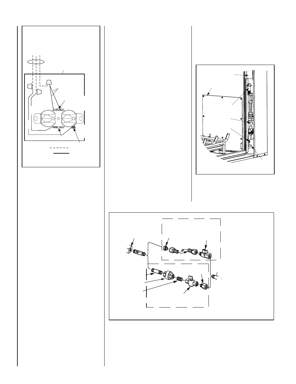
Step 6. CONNECTING GAS LINE
All.codes.require.a.shut-off.valve.mounted.in.
the.supply.line..The.orientation.of.the.shut-off.
valve. should. face. the. front.. .
Figure 37 . il-
lustrates.two.methods.for.connecting.the.gas.
supply...A.Sediment.Trap.is.recommended.to.
prevent.moisture.and.debris.in.gas.line.from.
damaging.the.valve.
The.flex-line.method.is.acceptable.in.the.U.S.A..
where.local.codes.permit,.however,.Canadian.
requirements.vary.depending.on.locality..Instal-
lation.must.be.in.compliance.with.local.codes...
These.appliances.are.equipped.with.a.gas.flex-
line.for.use.in.connecting.the.unit.to.the.gas.line...
See.Figure 37 for.flex-line.description...The.
flex-line.is.rated.for.both.natural.and.propane.
gas..A.manual.shut.off.valve.is.also.provided.
with.the.flex-line..
The.gas.control.valve.is.located.on.the.right.
side.of.the.unit.
When.using.solid.gas.line.connector,.access.
the.valve.by.removing.the.front.door.assembly.
on.the.valve.access.side.and.the.access.plate.
(refer to Figure 38).
The.millivolt.and.electronic.control.valve.has.a.
3/8".(10.mm).NPT.thread.gas.supply.inlet..
Bring.the.shutoff.valve.on.the.end.of.the.flex-line.
over.to.the.hard.pipe.and.tighten.with.wrenches.
from.above.through.the.firebox.opening.
Secure all joints tightly using appropriate
tools and sealing compounds (ensure propane
resistant compounds are used in propane ap-
plications). It is recommended to seal around
the gas line to prevent cold air leakage.
Piezo
Igniter
Gas Valve
ON/OFF Switch
Access Plate
Right Side
Modesty Panel
Hi-Lo
Extension Knob
Figure 38
Note: The gas supply line
must be installed in accor-
dance with building codes
by a qualified installer
approved and/or licensed
as required by the locality.
In the Commonwealth of
Massachusetts, installation
must be performed by a
licensed plumber or gas
fitter.
Gas
Valve
3/8" NPT x
Flare Fitting
3/8" Flex Tubing
3/8" Nipple
3/8" Union
3/8" Close
Nipple
3/8" Shut-off Valve
1/2" x 3/8"
Reducer
Gas
Stub
1/2" x 3/8" Flare
Shut-off Valve
Gas Solid Line Connector
Gas Flex Line Connector
*Sediment
Trap
3"
Min
Figure 37 -
GAS CONNECTION
Figure 36-
J-BOX WIRING
J-BOX/RECEPTIACLE
WIRING
120V, 60HZ, 1PH
Factory Wired
Field Wired
Junction Box
Tab Intact
Tab
Intact
n e
e r
G -
d n
u o r
G
e t i
h
W - l
a r t
u e
N 12
0
VA
C
- B
la
ck
Green
Ground
Screw
W
hi
te
Gr
ee
n
Neutral
Side of
Receptacle
Hot
Side of
Receptacle
Black