Caution – Milwaukee LSM40MP-2 User Manual
Page 21
21
Step 4. FIELD WIRING
CAUTION
Ground supply lead must be con-
nected to the wire attached to the
green ground screw located on
the outlet box. See
Figures 35 and
36
. Failure to do so will result in a
potential safety hazard. The appli-
ance must be electrically grounded
in accordance with local codes or,
in the absence of local codes, the
National Electrical Code, ANSI/
NFPA 70-latest edition. (In Canada,
the current CSA C22-1 Canadian
Electrical Code).
CAUTION: Label all wires prior to disconnec-
tion when servicing controls. Wiring errors can
cause improper and dangerous operation.
ATTENTION: Au moment de l'entretien des
commandes, étiquetez tous les fils avant de
les débrancher. Des erreurs de cáblage peu-
vent entraîner un fonctionnement inadéquat
et dangereux.
Verify proper operation after servicing.
S'assurer que l'appareil fonctionne adé-
quatement une fois l'entretien terminé.
Figure 34
Figure 35
Thermopile
TH
TP
TH
TP
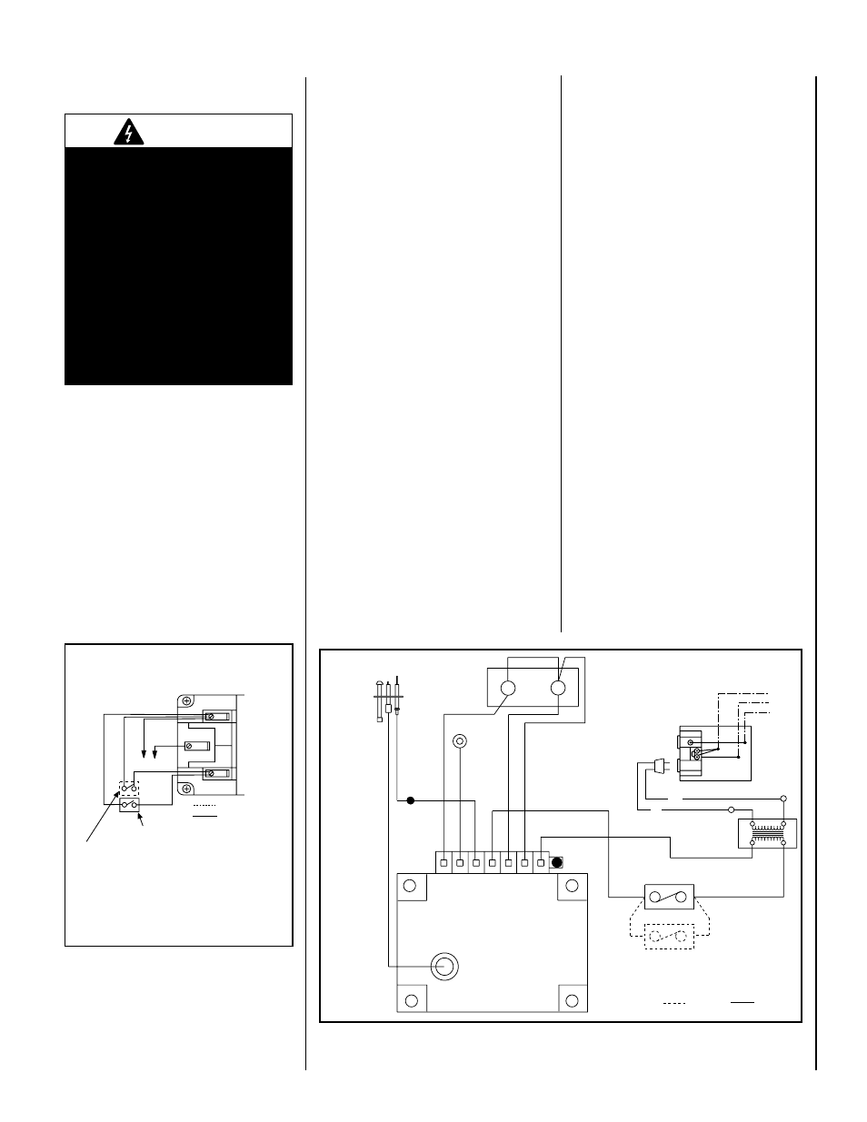
Millivolt Wiring Diagram
If any of the original wire as supplied must be replaced,
it must be replaced with
Type AWM 105° C – 18 GA. wire
*OR OPTIONAL WALL-MOUNTED ON/OFF SWITCH OR
OPTIONAL REMOTE CONTROL RECEIVER
*Turn the appliance-mounted ON/OFF burner control switch
to the OFF position if an optional
control switch is installed.
Factory Wired
Field Wired
Schematic Representation Only
APPLIANCE-MOUNTED ON/OFF SWITCH
ELECTRONIC
WIRING DIAGRAM
BLK
W
120 V.
24 V.
TRANSF
ELECTRONIC IGNITION
CONTROL BOARD
*WALL MOUNTED ON/OFF SWITCH (OPTIONAL)
OR REMOTE CONTROL RECEIVER
APPLIANCE MOUNTED
ON/OFF SWITCH
PILOT BURNER
IGNITER-SENSOR
ASSEMBLY
GAS VALVE
EV2
EV1
GROUND
CONNECTOR
GREEN LED
WHITE (6)
WH
ITE
(2
0)
OR
AN
GE
(2
0)
BLACK (20)
PU
RP
LE
(9
)
GR
EE
N (
12
)
BLUE (20)
BLACK (16)
WHITE
FIELD WIRED
FACTORY WIRED
*Turn The Appliance-Mounted ON/OFF Burner Control Switch
To The OFF Position If An Optional Control Switch Is Installed
Black
White
Ground
Junction Box
120 VAC
3..Remove.the..cover.plate's.knockout.and.then.
feed.the.power.supply.wire.through.the.knock-
out.opening.and.into.the.unit.junction.box.
4..Connect.the.black.power.supply.wire.to.the.
power outlet's.red.pigtail.lead.and.the.white.
power.supply.wire.to.the.
common terminal.of.
the.outlet.as.shown.in.
Figures 35 and 36..
5.. Connect the ground supply wire to the
pigtail lead attached to outlet's green
ground screw.
6...Appliance-mounted.ON/OFF.burner.control.
switch.(rocker.switch).is.factory.installed..
Optional.wall-mounted..switch,.or.one.of.
the.optional.remote.control.kits.may.also.
be.used..
7...If. wall-mounted. ON/OFF. control. is. to. be.
used,.mount.it.in.a.convenient.location.on.
a.wall.near.the.fireplace.
8..If.an.optional.control.is.to.be.used,.wire.it.in.
the.low.voltage.circuit.(see.
Figure 35).
Note: The supplied 15 feet of 2 conductor wire
has one end of each conductor connected in
parallel with the appliance mounted ON/OFF
burner control switch and the other end of each
conductor placed on top of the unit.
CAUTION: Do Not connect the optional wall
switch to a 120V power supply.
9..If. an. optional. control. switch. is. installed,.
turn.the.appliance-mounted.ON/OFF.burner.
control.switch.to.the.OFF.position.
10.After. the. wiring. is. complete,. replace. the.
cover.plate.
See Figure 36 for detailed
drawing of junction box /
receptacle wiring
Refer.to.Section.A.for.millivolt.appliances.and.
Section. B. for. electronic. appliances.. The. gas.
valve.is.set.in.place.and.pre-wired.at.the.factory.
on.both.models.
A. Millivolt Wiring (See Figure 34).–.
1...Appliance-mounted.ON/OFF.burner.control.
switch.(rocker.switch).is.factory.installed..
Optional. wall-mounted. . switch,. or. one. of.
the.optional.remote.control.kits.may.also.
be.used..
2..If.wall-mounted.ON/OFF.control.is.selected.
mount.it.in.a.convenient.location.on.a.wall.
near.the.fireplace.
3..Wire.the.control.switch.within.the.millivolt.
control.circuit..using.the.15.feet.of.2.conduc-
tor.wire.supplied.with.the.unit.
Note: The supplied 15 feet of 2 conductor wire
has one end of each conductor connected
to the gas valve circuit and the other end of
each conductor placed on top of the unit.
CAUTION: Do Not connect the optional wall
switch to a 120V power supply.
4. If. an. optional. control. switch. is. installed,.
turn.the.appliance-mounted.ON/OFF.burner.
control.switch.to.the.OFF.position.
B. Electronic Wiring
(See Figures 35 and 36)
Note: The electronic appliance must be con-
nected to the main power supply.
1..Route. a. 3-wire. 120Vac. 60Hz. 1ph. power.
supply.to.the.appliance.junction.box.
2..Remove.the.electrical.inlet.cover.plate.from.
the.side.of.the.unit.by.removing.the.plate's.
securing. screws. (see Figure 12 on Page
10).