Milwaukee LSM40MP-2 User Manual
Page 14
14
NOTE:.DIAGRAMS.&.ILLUSTRATIONS.ARE.NOT.TO.SCALE.
Figure 18
Vertical (Offset) Installation
Analyze. the. vent. routing. and. determine. the.
quantities.of.vent.sections.and.number.of.elbows.
required..Refer.to.Vertical Vent Figures and
Tables on Page 16..to.select.the.type.of.vertical.
installation.desired..Vent.sections.are.available.
in.net.lengths.of.4-1/2".(114.mm),.10-1/2".(267.
mm),.22-1/2".(572.mm),.34-1/2".(876.mm).and.
46-1/2".(1181.mm)..Refer.to.the.Vent Section
Length Chart on Page 13.for.an.aid.in.select-
ing.length.combinations..Elbows.are.available.
in.90°.and.45°.configurations..Refer.to.Figure
21 on Page 15 .for.the.SV8.E45.and.SV8.E90.
elbow.dimensional.specifications....
Where. required,. a.
telescopic vent section
(SV8LA)..may.be.used.to.provide.the.installer.
with.an.option.in.installing.in.tight.and..con-
fined.spaces.or.where.the.vent.run.made.up.
of. fixed. length. pieces. develops. a. joint. in. a.
undesirable.location,.or.will.not.build.up.to.the.
required. length.. The. SV8LA. Telescopic. Vent.
Section.has.an.effective.length.of.from.1-1/2".
(38.mm).to.6-3/4".(171.mm)..The.SV8LA..is.
fitted.with.a.dimpled.end.(identical.to.a.normal.
vent.section.component).and.a.plain.end.with.
3. pilot. holes.. Slip. the. dimpled. end. over. the.
locking.channel.end.of..a.standard..SV8.vent.
component.the.required.distance.and.secure.
with.three.screws.
Maintain a minimum 1" (25 mm) clearance
to combustible materials for all vertical ele-
ments. Clearances for all horizontal elements
are 3" (76 mm) on top, 1" (25 mm) on sides
and 1" (25 mm) on the bottom.
A..Frame ceiling opening -.Use.a.plumb.line.
from.the.ceiling.above.the.appliance.to.locate.
center. of. the. vertical. run.. Cut. and/or. frame.
an.opening,.13".x.13"..(330.mm.x.330.mm).
inside. dimensions,. about. this. center. mark.
(Figure 18).
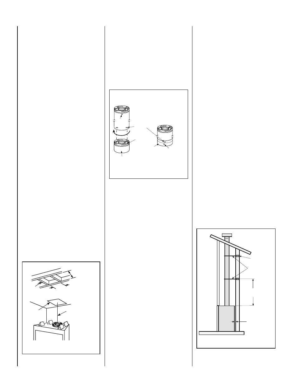
Figure 19
Align the dimple (four places) of the
upper vent section with the opening
of the locking incline channel on
the lower vent section or appliance
collar. Twist vent component clock-
wise to engage and seal until arrow
and dimple align.
Dimple
Locking Incline
Channel
Connected Vent
Sections
Arrow
Arrow
Appliance Collar or
Vent Section
Figure 20
Blocking
Support Straps
(Plumber's tape)
8 feet (2.4 m)
Maximum
1 inch (25.4
mm) minimum
clearance to
combustibles
Roof
Framing
Ceiling
Framing
Plumb
Bob
13” Min.
(330 mm)
13” Min.
(330 mm)
Push.the.vent.component.against.the.previous.
section. until. it. fully. engages,. then. twist. the.
component.clockwise.running.the.dimples.down.
and.along.the.incline.channels.until.they.seat.at.
the.end.of.the.channels..This seating position
is indicated by the alignment of the arrow and
dimple as shown in.Figure 19.
D.. Install firestop/spacer at ceiling -.When.
using.Secure.Vent,.use.SV8BF.firestop/spacer.
at.ceiling.joists..If.there.is.living.space.above.
the.ceiling.level,.the.firestop/spacer.must.be.
installed.on.the.bottom.side.of.the.ceiling..If.attic.
space.is.above.the.ceiling,.the.firestop/spacer.
must.be.installed.on.the.top.side.of.the.joist..
Route. the. vent. sections. through. the. framed.
opening. and. secure. the. firestop/spacer. with.
8d.nails.or.other.appropriate.fasteners.at.each.
corner.. Remember to maintain 1" (25 mm)
clearance to combustibles, framing members,
and attic or ceiling insulation when running
vertical chimney sections. Attic insulation
shield (H3908) may be used to obtain the
required clearances indicated here. See
installation accessories on Page 30. .The.gap.
between.the.vent.pipe.and.a.vertical.firestop.can.
be.sealed.with.non-combustible.caulking.
E..Support the vertical vent run sections -
Note - Proper venting support is very important.
The weight of the vent must not be supported
by the fireplace in any degree..
Support. the. vertical. portion. of. the. venting.
system.every.8.feet.(2.4.m).above.the.fireplace.
vent.outlet..
B.. Attach vent components to appliance
-.Secure Vent.SV8.direct-vent.system.compo-
nents.are.unitized.concentric.pipe.components.
featuring.positive.twist.lock.connections.(see
Figure 19)...
All.of.the.appliances.covered.in.this.document.
are.fitted.with.collars.having.locking.inclined.
channels..The.dimpled.end..of.the.vent.com-
ponents.fit.over.the.appliance.collar.to.create.
the.positive.twist.lock.connection.
To.attach.a.vent.component.to.the.appliance.
collar,.align.the.dimpled.end.over.the.collar,.
adjusting. the. radial. alignment. until. the. four.
locking. dimples. are. aligned. with. the. inlet. of.
the.four.inclined.channels.on.the.collar.(refer to
Figure 19)...Push.the.vent.component.against.
the.collar.until.it.fully.engages,.then.twist.the.
component. clockwise,. running. the. dimples.
down.and.along.the.incline.channels.until.they.
seat.at.the.end.of.the.channels...The.unitized.
design.of.the.Secure Vent™.components.will.
engage.and.seal.both.the.inner.and.outer.pipe..
without.the.need.for.sealant.or.screws...If.desired.
a.#6.x.1/2".screw.may.be.used.at.the.joint,.but.
it.is.not.required.as.the.pipe.will.securely.lock.
when.twisted.
C. Attach vent components to each other
-. Other. vent. sections. may. be. added. to. the.
previously.installed.section.in.accordance.with.
the. requirements. of. the. vertical. vent. figures.
and.tables...To.add.another.vent.component.
to.a.length.of.vent.run,.align.the.dimpled.end.
over.the.inclined.channel.end.of.the.previously.
installed.section,.adjusting.the.radial.alignment.
until.the.four.locking.dimples.are.aligned.with.
the.inlets.of.the.four.incline.channels.of.the.
previous.section..