Figure 7 – Milwaukee LSM40MP-2 User Manual
Page 7
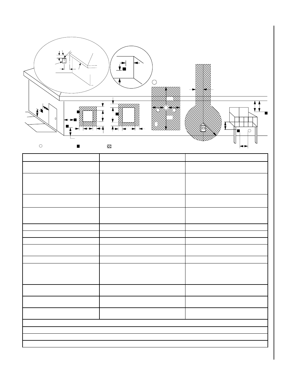
NOTE:.DIAGRAMS.&.ILLUSTRATIONS.ARE.NOT.TO.SCALE.
7
ExTERIOR HORIZONTAL VENT TERMINATION CLEARANCE REQUIREMENTS
Minimum Clearances
Canadian Installation *
US Installation **
A. =. Clearance. above. grade,. veranda,. porch,. deck.
or.balcony.
12.inches.(30.cm).*
12.inches.(30.cm).**
B. =. Clearance. to. window. or. door. that. may. be.
opened.
6.in..(15.2.cm).for.appliances.<.10,000.BTU/hr.(3kW),.
12.in..(30.cm).for.appliances.>.10,000.BTU/hr.(3kW).and.<..
100,000.BTU/hr.(30kW),..36.inches.(91.cm).for.appliances.
>.100,000.BTU/hr.(30kW)*
6.in..(15.2.cm).for.appliances.<.10,000.BTU/hr.(3kW),.
9.in..(23.cm).for.appliances.>.10,000.BTU/hr.(3kW).and.<..
50,000.BTU/hr.(15kW),..12.inches.(30.cm).for.appliances.
>.50,000.BTU/hr.(15kW)*
C.=.Clearance.to.permanently.closed.window
12. inches. (305. mm). recommended. to. prevent. window.
condensation
9.inches.(229.mm).recommended.to.prevent.window.
condensation
D.=.Vertical.clearance.to.ventilated.soffit.located.
above.the.terminal.within.a.horizontal.distance.of..36.
in..(91.4cm).from.the.center.line.of.the.terminal
24.inches.(61.0.cm)
24.inches.(61.0.cm)
E.=.Clearance.to.unventilated.soffit
24.inches.(61.0.cm)
24.inches.(61.0.cm)
F.=.Clearance.to.outside.corner
5.inches.(12.7.cm)
5.inches.(12.7.cm)
G.=.Clearance.to.inside.corner
36".(91.4.cm)
24.inches.(61.0.cm)
H.=.Clearance.to.each.inside.of.center.line.extended.
above.meter./.regulator.assembly
3.feet.(91.cm).within.a.height.of.15.feet.above.the.meter./.
regulator.assembly.*
3.feet.(91.cm).within.a.height.of.15.feet.above.the.meter.
/.regulator.assembly.**
I.=.Clearance.to.service.regulator.vent.outlet
3.feet.(91.cm).*
3.feet.(91.cm).**
J. =. Clearance. to. non-mechanical. air. supply. inlet.
to.building.or.the.combustion.air.inlet.to.any.other.
appliance
6.in..(15.2.cm).for.appliances.<.10,000.BTU/hr.(3kW),.12.
in..(30.cm).for.appliances.>.10,000.BTU/hr.(3kW).and.<..
100,000.BTU/hr.(30kW),..36.inches.(91.cm).for.appliances.
>.100,000.BTU/hr.(30kW)*
6.in..(15.2.cm).for.appliances.<.10,000.BTU/hr.(3kW),.9.
in..(23.cm).for.appliances.>.10,000.BTU/hr.(3kW).and.<..
50,000.BTU/hr.(15kW),..12.inches.(30.cm).for.appliances.
>.50,000.BTU/hr.(15kW)*
K.=.Clearance.to.mechanical.air.supply.inlet
6.feet.(1.83.meters).*
3.feet.(91.cm).above,.if.within.10.feet.(3.m).horizon-
tally**
L. =. Clearance. above. paved. sidewalk. or. paved.
driveway.located.on.public.property
7.feet.(2.13.m).‡
7.feet.(2.13.m).‡
M. =. Clearance. under. veranda,. porch,. deck. or.
balcony
18.in..(46.0.cm).*.‡
18.in..(46.0.cm).**.‡
*.In.accordance.with.the.current.CSA-B149.1.National.Gas.and.B149.2.Propane.Installation.Code.-.Latest.Editions.
**.In.accordance.with.the.current.ANSI.Z223.1./.NFPA.54.National.Fuel.Codes.-.Latest.Edition.
‡.A.vent.shall.not.terminate.directly.above.a.sidewalk.or.paved.driveway.which.is.located.between.two.single.family.dwellings.and.serves.both.dwellings.
*‡.Only.permitted.if.veranda,.porch,.deck.or.balcony.is.fully.open.on.a.minimum.2.sides.beneath.the.floor.
Figure 7
NOTE: Local Codes Or Regulations May Require
Different Clearances.
NOTE: Location Of The Vent Termination Must Not
Interfere With Access To The Electrical Service.
V
V
V
V
V
F
C
B
B
A
B
H
M
I
X
V
D
V
A
A
A
V
L
B
J
X
E
V
A
G
*18”
18”
B
C
C
C
K
X
�
�
�
* See Item D in the Text Below.
Center Line
of Termination
Exterior Wall
Horizontal
Termination
Ventilated Soffit
Inside Corner
DETAIL D
Inside
Corner Detail
Operable
Window
Fixed
Closed
Window
= 9" in U.S.
= 12" in Canada
3 ft.
3 ft.
= Air Supply Inlet
= Vent Terminal
= Area where Terminal is NOT permitted
24"
36"