Milwaukee LSM40MP-2 User Manual
Page 11
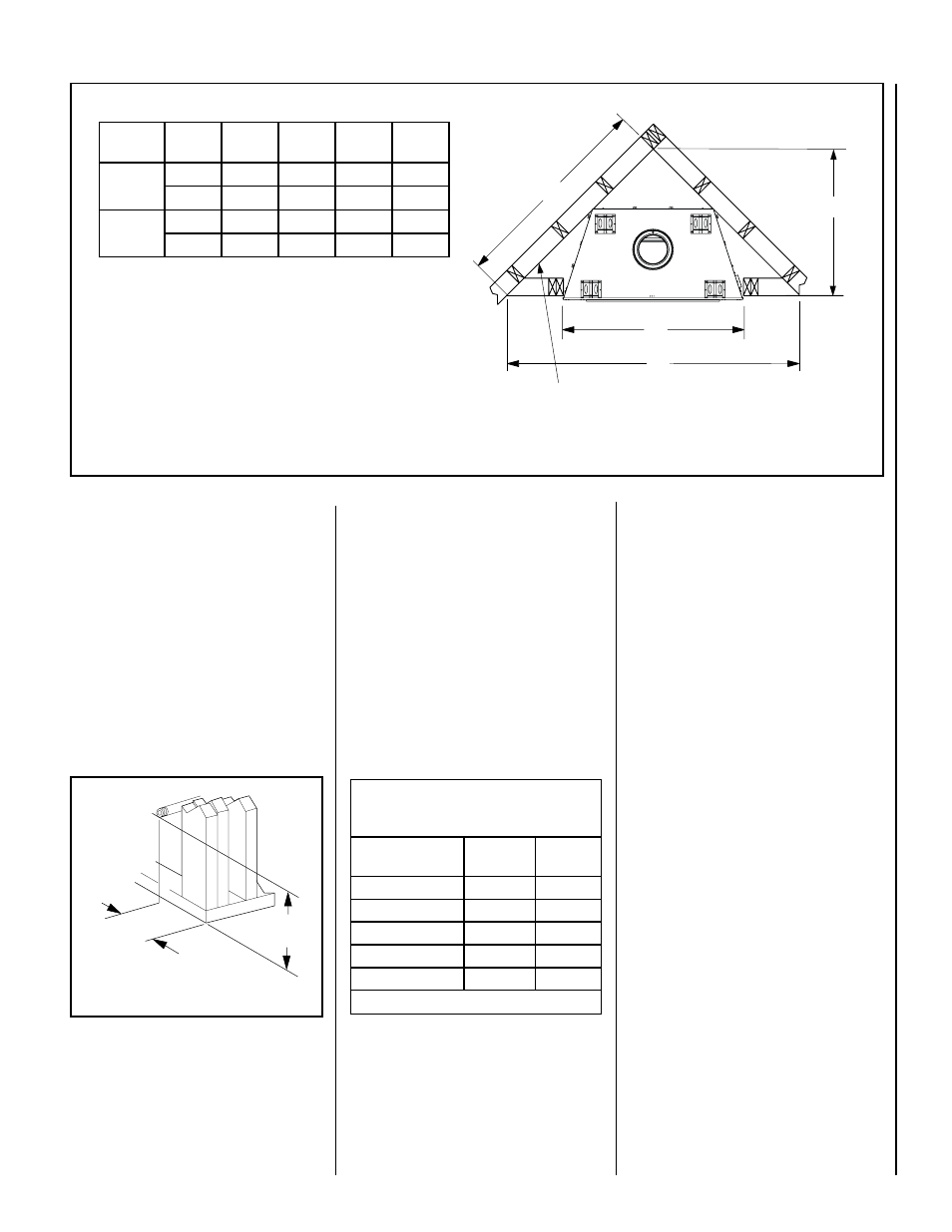
NOTE:.DIAGRAMS.&.ILLUSTRATIONS.ARE.NOT.TO.SCALE.
11
C
Back wall of chase/enclosure
(including any finishing materials)
D
A
B
Model
No.
A
B
C
D
LSM40-2
in.
50-5/8
83-5/8
59-1/8
41-7/8
mm
1286
2124
1502
1064
LSM45-2
in.
56-3/4
89-7/8
63-1/2
44-7/8
mm
1441
2283
1613
1140
Figure 13 - Corner Framing with Square Termination (SV8HTS)
Schedule 40
Black Iron Pipe
Inside Diameter (Inches)
Schedule 40 Pipe
Length (feet)
Natural
Gas
Propane
Gas
0-10
1/2
3/8
10-40
1/2
1/2
40-100
1/2
1/2
100-150
3/4
1/2
150-200
3/4
1/2
Table 6
Proper Sizing of Gas Line
Properly. size. and. route. the. gas. supply. line.
from.the.supply.regulator.to.the.area.where.the.
appliance.is.to.be.installed.per.requirements.
outlined.in.the.National.Fuel.Gas.Code,.NFPA.
54.-.latest.edition.(USA).or.CAN/CSA-B149.1.
-.latest.edition.(Canada)..
Notes:
•. All. appliances. are. factory-equipped. with.
a.flexible.gas.line.connector.and.1/2.inch.
shutoff.valve.(see.
Figure 37.on.Page 22).
•. See.
Massachusetts Requirements.on.Page
4..for.additional.requirements.for.installations.
in.the.state.of.Massachusetts.in.the.USA.
•. The.gas.supply.line.should.Not.be.connected.
to.the.appliance.until.
Step 6.(Page 22).
•. A.pipe.joint.compound.rated.for.gas.should.be.
used.on.the.threaded.joints.
Ensure propane
resistant compounds are used in propane
applications..Be.very.careful.that.the.pipe.
compound.does.not.get.inside.the.pipe.
•. It.is.recommended.to.install.a.sediment.trap.
in.the.supply.line.as.close.as.possible.to.the.
appliance.(see.
Figure 37)...Appliances.using.
propane.should.have.a.sediment.trap.at.the.
base.of.the.tank.
•. Check.with.local.building.official.for.local.
code.requirements.(i.e..are.below.grade.pen-
etrations.of.the.gas.line.allowed?,.etc.).
IMPORTANT: If propane is used, be aware that
if tank size is too small (i.e. under 100-lbs, if
this is the only gas appliance in the dwelling.
Ref. NPFA 58), there may be loss of pressure,
resulting in insufficient fuel delivery (which
can result in sooting, severe delayed ignition
or other malfunctions). Any damage resulting
from an improper installation, such as this, is
not covered under the limited warranty.
Right Side
Front Corner
Of Fireplace
Framing
6-1/4”
(159 mm)
19-5/8”
(498 mm)
Figure 14
Step 2. ROUTING GAS LINE
Route.a.1/2".(13.mm).gas.line.along.the.inside.
of.the.right.side.framing.as.shown.in
Figure
14...Gas.lines.must.be.routed,.constructed.and.
made.of.materials.that.are.in.strict.accordance.
with.local.codes.and.regulations.
All. appliances. are. factory-equipped. with. a.
flexible.gas.line.connector.and.1/2.inch.shutoff.
valve..(See Step 6 on Page 22).
The. incoming. gas. line. should. be. piped. into.
the.valve.compartment.and.connected.in.one.
of.the.two.methods.as.shown.in.Figure 37.on.
Page 22.
Never. use. galvanized. or. plastic. pipe.. . Refer.
to.
Table 6.for.proper.sizing.of.the.gas.sup-
ply.line,.if.black.iron.pipe.is.being.used..Gas.
lines.must.be.routed,.constructed.and.made.
of.materials.that.are.in.strict.accordance.with.
local.codes.and.regulations....We.recommend.
that.a.qualified.individual.such.as.a.plumber.or.
gas.fitter.be.hired.to.correctly.size.and.route.
the.gas.supply.line.to.the.appliance..Installing.
a.gas.supply.line.from.the.fuel.supply.to.the.
appliance.involves.numerous.considerations.of.
materials,.protection,.sizing,.locations,.controls,.
pressure,.sediment,.and.more..Certainly.no.one.
unfamiliar.and.unqualified.should.attempt.sizing.
or.installing.gas.piping.