Milwaukee LSM40MP-2 User Manual
Page 6
6
NOTE:.DIAGRAMS.&.ILLUSTRATIONS.ARE.NOT.TO.SCALE.
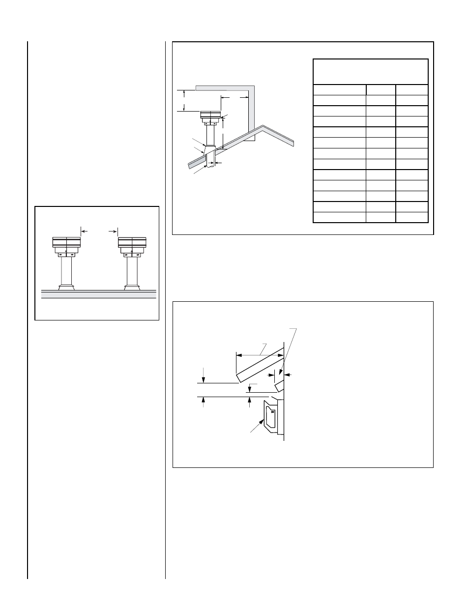
3"
(76 mm)
Termination Kit
Combustible Projection
greater than 2-1/2 inches in length
Horizontal Vent Termination Clearances
Combustible Projection
2-1/2 inches or less in length
24"
(610 mm)
Ventilated Or
Unventilated Soffit
Figure 6 - Side Elevation View
See Figure 30 on Page 18 for the recess allowances, into
exterior walls, of the square horizontal terminations.
Termination Heights For Vents
Above Flat Or Sloped Roofs
Ref. NFPA 54 / ANSI Z223.1
Roof Pitch
* Feet
* Meters
Flat.to.6/12
1.0
0.3
6/12.to.7/12
1.25
0.38
7/12.to.8/12
1.5
0.46
8/12.to.9/12
2.0
0.61
9/12.to.10/12
2.5
0.76
10/12.to.11/12
3.25
0.99
11/12.to.12/12
4.0
1.22
12/12.to.14/12
5.0
1.52
14/12.to.16/12
6.0
1.83
16/12.to.18/12
7.0
2.13
18/12.to.20/12
7.5
2.29
20/12.to.21/12
8.0
2.44
The.vent./.air.intake.termination.clearances.
above.the.high.side.of.an.angled.roof.is.as.
shown.in.the.following.chart:
12
x
Roof Pitch is x/12
2 FT
MIN.
2 FT MIN.
Lowest
Discharge
Opening
H*
*H = MINIMUM HEIGHT FROM ROOF TO
LOWEST DISCHARGE OPENING OF VENT
TERMINATION HEIGHTS FOR VENTS ABOVE
FLAT OR SLOPED ROOFS
Horizontal Overhang
Vertical
Wall
Vent
Termination
Storm Collar
Concentric
Vent Pipe
Flashing
1 inch (25.4 mm) Minimum
Clearance to Combustibles
Vertical Vent Termination Clearances
Figure 5
VENT TERMINATION CLEARANCES
These instructions should be used as a
guideline and do not supersede local codes
in any way. Install vent according to local
codes, these instructions, the current National
Fuel Gas Code (ANSI-Z223.1) in the USA or
the current standards of CAN/CSA-B149.1 in
Canada.
Vertical Vent Termination Clearances
Terminate.multiple.vent.terminations.according.
to.the.installation.codes.listed.above..Also.see.
Figure 4.
Terminate.single..vent.caps.relative.to.building.
components.according.to.Figure 5.
Horizontal Vent Termination Clearances
The.horizontal.vent.termination.must.have.a.minimum.of.3".(76.mm).clearance.to.any.overhead.
combustible.projection.of.2-1/2".(64.mm).or.less.(see..
Figure 6). .For.projections.exceeding.2-1/2"..
(64.mm),.see.
Figure 7..For.additional.vent.location.restrictions.refer.to.Figure 7 on Page 7.
12”
(305mm)
Minimum
Figure 4 - Multiple Terminations