Milwaukee LSM40MP-2 User Manual
Page 17
NOTE:.DIAGRAMS.&.ILLUSTRATIONS.ARE.NOT.TO.SCALE.
17
Vertical
Rise
SV8E90
Elbow
Horizontal / Inclined Run
SV8HTS
Termination
Shown
Firestop/Spacer
SV8 L6/12/24/36/48
Vent Sections
Support Bracket Spacing
Every 3 ft (914 mm)
SV8HTS
Termination
Shown
Support
Brackets
Building
Support
Framing
Ceiling
Fireplace
Exterior
Wall
Exterior
Wall
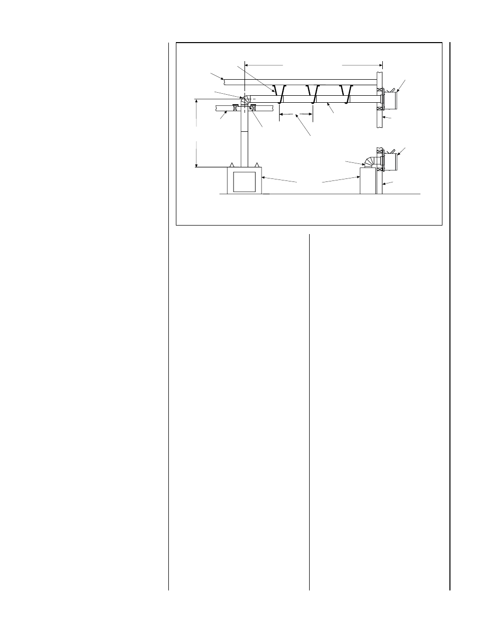
TYPICAL HORIZONTAL VENT INSTALLATION
2-1/2 Foot Vertical
Vent (min.)
Figure 28
Support the vertical portion of the venting system
every 8 feet (2.4m) above the fireplace vent outlet.
Push. the. vent. component. against. the. collar.
until.it.fully.engages,.then.twist.the.component.
clockwise,.running.the.dimples.down.and.along.
the.incline.channels.until.they.seat.at.the.end.
of. the. channels.. . The. unitized. design. of. the.
Secure Vent.components.will.engage.and.seal.
both.the.inner.and.outer.pipe.elements.with.the.
same.procedure...Sealant.and.securing.screws.
are.not.required.
E. Attach vent components to each other -.Other.
vent.sections.may.be.added.to.the.previously.
installed.section.in.accordance.with.the.require-
ments.of.the.vent.tables...To.add.another.vent.
component.to.a.length.of.vent.run,.align.the.
dimpled.end.of.the.component.over.the.inclined.
channel.end.of.the.previously.installed.section,.
adjusting.the.radial.alignment.until.the.four.lock-
ing.dimples.are.aligned.with.the.inlets.of.the.four.
incline.channels.of.the.previous.section...Push.
the.vent.component.against.the.previous.section.
until.it.fully.engages,.then.twist.the.component.
clockwise.running.the.dimples.down.and.along.
the.incline.channels.until.they.seat.at.the.end.of.
the.channels..This seating position is indicated
by the alignment of the arrow and dimple as
shown in.Figure 19 on Page 14.
F..Install firestop/spacer at ceiling -
When.using.
Secure Vent,.use.SV8BF.firestop/
spacer.at.ceiling.joists..If.there.is.living.space.
above.the.ceiling.level,.the.firestop/.spacer.must.
be.installed.on.the.bottom.side.of.the.ceiling..
If.attic.space.is.above.the.ceiling,.the.firestop/.
spacer. must. be. installed. on. the. top. side. of.
the.joist...Route.the.vent.sections.through.the.
framed.opening.and.secure.the.firestop/spacer.
with.8d.nails.or.other.appropriate.fasteners.at.
each.corner.
Remember to maintain 1" (25 mm) clearance
to combustibles, framing members, and attic
or ceiling insulation when running vertical
chimney sections.
G..Support the vertical run sections -
See.
Section E.on Page 14.
H. Change vent direction - .At.transition.from.or.
to.a.horizontal/inclined.run,.install.the.SV8E45.
and.SV8E90.elbows.in.the.same.manner.as.the.
straight.vent.sections...The.elbows.feature.a.twist.
section.to.allow.them.to.be.routed.about.the.
center.axis.of.their.initial.collar.section.to.align.
with.the.required.direction.of.the.next.vent.run.
element..Twist elbow sections in a clockwise
direction only so as to avoid the possibility of
unlocking any of the previously connected vent
sections (see.Figure 19 on Page 14).
I..Continue installation of horizontal/inclined
sections -..Continue.with.the.installation.of.the.
straight.vent.sections.in.horizontal/inclined.run.
as.described.in.
Step E..Install.support.straps.
every.3.feet.(1914.mm).along.horizontal/inclined.
vent.runs.using.conventional.plumber’s.tape..
See.
Figure 28,.it is very important that the
horizontal/inclined run be maintained in a
straight (no dips) and recommended to be in
a slightly elevated plane, in a direction away
from the fireplace of 1/4" rise per foot (20 mm
per meter) which is ideal,.though.rise.per.foot.
run.ratios.that.are.smaller.are.acceptable.all.the.
way.down.to.at.or.near.level...
It is important to maintain the required clear-
ances to combustibles: 1" (25 mm) at all sides
for all vertical runs; and 3" (76 mm) at the top,
1" (25 mm) at sides, and 1" (25 mm) at the
bottom for all horizontal/inclined runs.
Use. a. carpenter’s. level. to. measure. from. a.
constant.surface.and.adjust.the.support.straps.
as.necessary..
HORIZONTAL (OUTSIDE WALL)
TERMINATION SYSTEM
See.
Figures 28, 31, 32 and 33 on Pages 17,
19 and 20 and.their.associated.Horizontal.Vent.
Table. which. illustrate. the. various. horizontal.
venting. configurations. that. are. possible. for.
use. with. these. appliances.. .
Secure Vent™.
pipe.applications.are.shown.in.these.Figures...
A. Horizontal. Vent. Table. summarizes. each.
system’s.minimum.and.maximum.vertical.and.
horizontal. length. values. that. can. be. used. to.
design. and. install. the. vent. components. in. a.
variety.of.applications..
The.horizontal.vent.system.terminates.through.
an.outside.wall..Building.Codes.limit.or.prohibit.
terminating.in.specific.areas..Refer.to.Figure 7
on Page 7.for.location.guidelines.
Secure Vent.SV8.direct-vent.system.compo-
nents.are.unitized.concentric.pipe.components.
featuring.positive.twist.lock.connection,.(refer
to Figure 19.on Page 14)...All.of.the.appli-
ances.covered.in.this.document.are.fitted.with.
collars.having.locking.inclined.channels..The.
dimpled.end.of.the.vent.components.fit.over.
the.appliance.collar.to.create.the.positive.twist.
lock.connection.
A..Plan the vent run -.
Analyze.the.vent.routing.and.determine.the.
types. and. quantities. of. sections. required.......
4-1/2".(114.mm),.10-1/2".(267.mm),.22-1/2".
(572.mm),.34-1/2".(876.mm).and.46-1/2".(1181.
mm). net. section. lengths. are. available.. . It. is.
recommended.that.you.plan.the.vent.lengths.
so.that.a.joint.does.not.occur.at.the.intersection.
of.ceiling.or.roof.joists..Make.allowances.for.
elbows.as.indicated.in.Figure 21 on Page 15..
Maintain a minimum 1" (25 mm) clearance
to combustibles on the vertical sections.
Clearances for the horizontal runs are; 3"
(76 mm) on top, 1" (25 mm) on sides, and
1" (25 mm) at the bottom.
B..Frame exterior wall opening -.
Locate. the. center. of. the. vent. outlet. on.
the. exterior. wall. according. to. the. dimen-
sions. shown. in.
Figure 12 on Page 10...
Cut. and/or. frame. an. opening,. 15". x. 13"..
(381.mm.x.330.mm).inside.dimensions,.with.
9".above.center.and.7".below.center.
C.. Frame ceiling opening -. If. the. vertical.
route.is.to.penetrate.a.ceiling,.use.plumb.line.
to.locate.the.center.above.the.appliance..Cut.
and/or.frame.an.opening,.13".x.13".(330.mm.x.
330.mm).inside.dimensions,.about.this.center.
(refer.to.Figure 18 on Page 14).
D. Attach vent components to appliance - To.
attach.a.vent.component.to.the.appliance.collar,.
align.the.dimpled.end.over.the.collar,.adjust-
ing.the.radial.alignment.until.the.four.locking.
dimples.are.aligned.with.the.inlets.of.the.four.
incline.channels.on.the.collar.(refer to Figure
19..on Page 14).