Milwaukee LSM40MP-2 User Manual
Page 18
18
NOTE:.DIAGRAMS.&.ILLUSTRATIONS.ARE.NOT.TO.SCALE.
Horizontal terminations have been designed to perform in a wide range of weather condi-
tions. Our terminations meet or exceed industry standards.
When selecting the locations of your horizontal terminations, do not place the termina-
tion where water from eaves and adjoining rooflines may create a heavy flow of cascad-
ing water onto the termination cap. If the cap must be placed where the possibility of
cascading water exists, it is the responsibility of the builder to direct the water away
from the termination cap by using gutters or other means.
Take care to carefully follow the installation instructions for the termination, including
the use of silicone caulking where required.
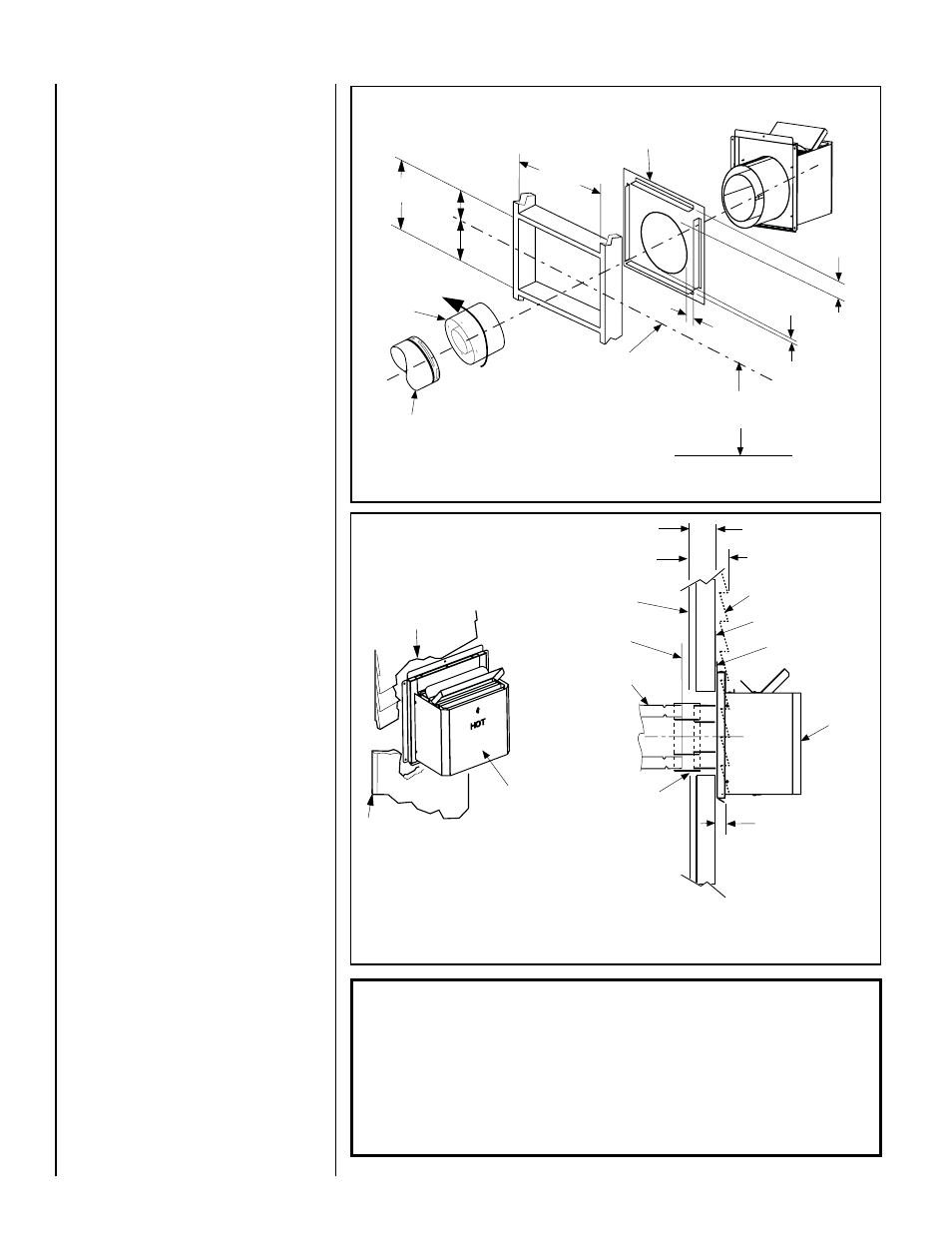
Figure 29
Installing the Square Horizontal Termination (SV8HTS)
Firestop/Spacer (SV8HF) shown
on the exterior side of the wall. It
may also be installed on the
interior side.
SV8HTS
Termination
Shown.
13"
(330mm)
8 ¹⁄₂"
(216)
6 ¹⁄₂"
(165 mm)
15"
(381 mm)
Note: Centerline of Vent Piping is
NOT the Same as the Centerline of
the Framed Opening.
6 to 48 inch Vent Section,
Telescopic vent section.
See Figure 9 on page 7
for Min. Distance to Base
of Appliance.
Base of Appliance
3"
(76 mm)
Adapter
SV8RCH
1"
(25 mm)
1"
(25 mm)
Figure 30 - Wall Thickness and Horizontal Termination Requirements
u
For wall thicknesses greater than
8-1/2 inches, see Table 8
u
Siding
Stucco
1-1/4” Maximum Recess of
Square Termination into
Exterior Finishing Material
Exterior Surface of
Framing
5 in. to 8-1/2 in.
(127 to 216 mm)
Exterior Surface of Siding
Minimum wall thickness
5 in. (127 mm)
Interior Surface of
Finished Wall
Maximum wall thickness
8-1/2 in. (216 mm)
SV8HTS
Square Termination
shown
Maximum Extent of
Vent Run Sections
Relative to Exterior
Surface of Framing
Last Vent Section. Use
T e l e s c o p i c V e n t
Section (SV8LA), If
Necessary
Adapter
SV8RCH
SV8HTS
Square Termination
Shown
Venting Connection and Exterior Wall Recessing
of the Horizontal Square Termination (SV8HTS).
See Figure 12 on Page 10 for Minimum
Distance to Base of Appliance
J..Assemble vent run to exterior wall -.If.not.
previously.measured,.locate.the.center.of.the.
vent.at.the.exterior.wall...Prepare.an.opening.
as. described. in.
Step B.. . Assemble. the. vent.
system.to.point.where.the.terminus.of.the.last.
section.is.within.5.in..(127.mm).to.8-1/2.in..(216.
mm).inboard.of.the.exterior.surface.to.which.
the.SV8HTS.termination.is.to.be.attached,.see.
Figure 30 and Table 8...
If.the.terminus.of.the.last.section.is.not.within.
this.distance,.use.the.telescopic vent section
SV8LA, as.the.last.vent.section..For.wall.thick-
nesses.greater.than.that.shown.in.
Figure 30,.
refer.to.Table 8 on Page 19..This.table.lists.
the.additional.venting.components.needed.(in.
addition.to.the.termination.and.adaptor).for.a.
particular.range.of.wall.thicknesses.
K.. Attach termination adaptor -. Attach. the.
adaptor.(adaptor.-.SV8RCH.-.provided.with.the..
termination).to.the.vent.section.or.telescoping.
vent.section),.or.elbow.as.shown.in.Figure 29
in.the.same.manner.as.any.SV.vent.component.
(refer.to.Step E).
L.. Install Firestop/Spacer at exterior wall
-.When.using.the.square termination,.install..
SV8HF.Firestop/Spacer.over.the.opening.at.the.
exterior.side.of.the.framing,.long.side.up,.with.
the.3.inch.spacer.clearance.at.the.top.as.shown.
in.Figure 29,.and.nail.into.place.
(The. Firestop/Spacer. may. also. be. installed.
over. the. opening. at. the. interior. side. of. the.
framing).
M. Install the square termination (SV8HTS)-..
For. the. last. step,. from. outside. the. exterior.
wall,.slide.the.collars.of.the.termination.onto.
the.adaptor.(the.outer.over.the.outer.and.the.
inner. inside. the. inner). until. the. termination.
seats.against.the.exterior.wall.surface.to.which.
it.will.be.attached...Orient.the.housing.of.the.
termination.with.the.arrow.pointed.upwards...
Secure.the.termination.to.the.exterior.wall...The
horizontal termination must not be recessed
into the exterior wall or siding.by more than
the 1-1/4" (32 mm) as shown in.Figure 30.
IMPORTANT: The vent termination is hot
while in operation and for a period of time
following the use of the fireplace. Young
children should be carefully supervised
when they are in the same area as a hot
termination.