1. setup flow chart – Miller Electric Welder User Manual
Page 113
OM-196 188 Page 107
SECTION 14 – SETUP
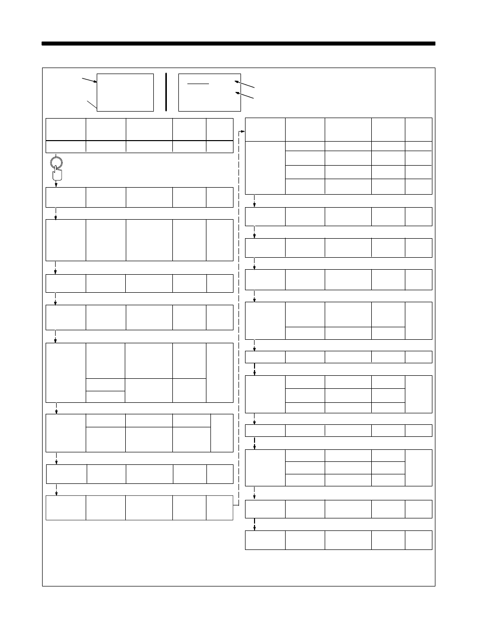
14-1. Setup Flow Chart
>Memory
No Reset
No Reset
14-12
Program
Reset
System
Reset
Total
Reset
>Wiretype
Wire Type
Hardwire/
Hardwire
14-10
Softwire
>Arc Start
Arc Start
Standard
Standard
14-7
Type
Hot Start
Soft Start
>Monitor
Arc Volts
Off/On
Off
14-19
Range
0.1 - 9.9
2.0 Volts
Sec
0.1 - 25
1.0 Sec.
>Program
Remote Off/On
Off
14-15
Select
>Shutdown
Arc Start/
Off/On
On
14-13
Volt Sense
>Access
Code
Off/On
Off
14-3
Display
Features
Settings
Default
Section
Selection
>Mig Type
Voltage
DVC On/Off
Off
14-4
Correction
>Voltage
Control
Internal
Internal
14-6
Feedback
Volt Sense
>Arc Time
Run Hours
0–9999.99
14-8
Hours
0–999,999
Cycles
No Reset
No Reset
Reset
1
Display Selections
2
Features
3
Settings
To set up features that customize operation, use the setup
displays. Features that can be customized are as follows:
Access
Mig Type
Aux Out
Voltage
> Volt Min
10.0 Volt
1
Display
Features
Settings
Default
Section
Selection
>Name
Card
Off/On
On
14-14
Programs
>Wire Feed
Display
IPM/MPM
IPM
14-9
Motor Type
Standard
Standard
Low Speed
High Speed
Press Mode Select To
Go To Next Setup Dis-
play
>Aux Output Auxiliary
Output On
Never
14-5
Output
w/Feeder
w/Arc
w/Weld Cycle
Never
>Stick
Stick Check
Off/On
Off
14-20
>Jog IPM
Robot Jog
Remote/Local
Local
Local Jog
IPM
50 - 780
200
14-17
2
3
Example Setup
Pendant Display
>Flow
Detect Flow
Off/On
Off
14-18
>Display
Actual
Command
14-11
Amps
Command
>Ramps
Program
Number
1
14-21
Start
Off/On
Off
Crater
Off/On
Off
>Exit
Exit Setup
Press
Menu Now
14-23
>Software
Version
14-22
Number