MITSUBISHI ELECTRIC DX-NT400E User Manual
Page 17
ENGLISH
17
•••••••••••••••••••••••••••••••••••••••••••••••••••••••••••••••••••••••••••••••••••••••••••••••••••••••• Attaching/Removing HDD
8. Attach the top cover of the HDD tray.
• To attach the top cover, put the hooks of the top cover in
the openings of the HDD tray.
• Use the 2 screws that were removed in step 1.
• Make sure that the lead is not caught in the top cover.
♦
When attaching additional HDD:
1. Remove the top cover of the HDD tray.
• Remove the 2 screws and lift the top cover.
2. Remove the HDD holder on the left side of the HDD tray.
• Remove the 4 screws attached to the HDD holder to remove
the HDD holder.
3. Follow the steps 3 and 4 in “
♦
When attaching one HDD:”
to attach the HDD holder on the side of the additional HDD,
and then attach it to the HDD tray.
• Use the supplied 4 screws to attach the HDD holder.
• Set the jumper of the additional HDD to “SLAVE.” Refer to
the instruction book of HDD for setting the jumper.
• The leads should not be caught in the HDD holder or the
HDD.
4. Connect the outer connector of the ATA LEAD to the
additional HDD.
• Make sure that the ATA LEAD between the HDDs is clamped.
(C)
5. Connect the POWER LEAD to the additional HDD.
• Make sure that the POWER LEAD between the HDDs is
clamped. (D)
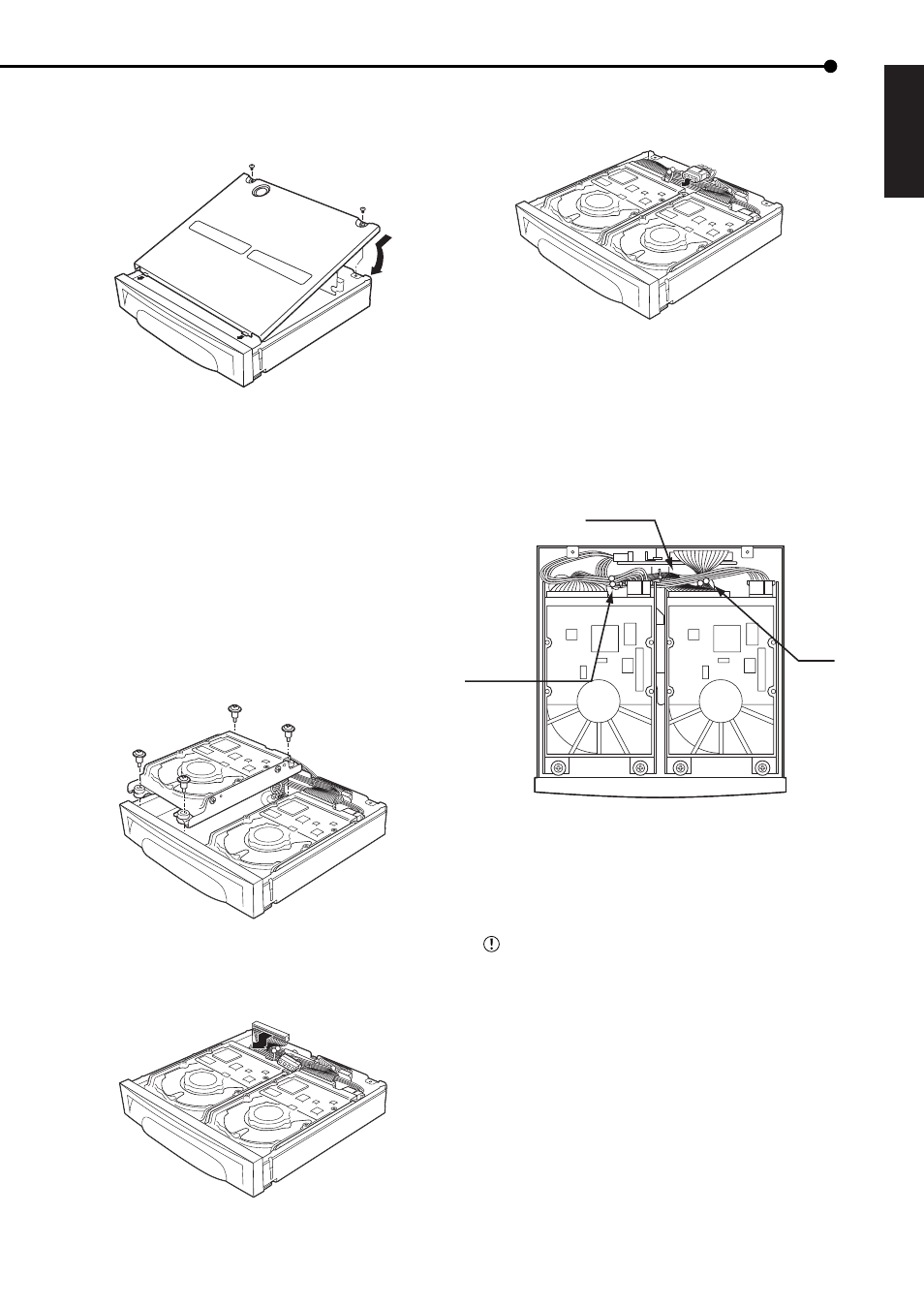
6. Check the wiring.
A: The lead between the PCB and the HDD is clamped.
B, D: The POWER LEAD which is connected to the HDD is
clamped.
C: The ATA LEAD is clamped.
E: Push the POWER LEAD and the ATA LEAD between the
middle connector and the outer connector into the space
between the PCB and the HDD.
A
E
B, C, D
7. Attach the top cover of the HDD tray.
• To attach the top cover, put the hooks of the top cover in
the openings of the HDD tray.
• Use the 2 screws that were removed in step 1.
• Make sure that the lead is not caught in the top cover.
Be sure to carry out HDD SELF TEST after
attaching the HDD. (See the next page.)