Operation – MITSUBISHI ELECTRIC MR-J2S- CL User Manual
Page 87
4 - 4
4. OPERATION
(f) Home position return
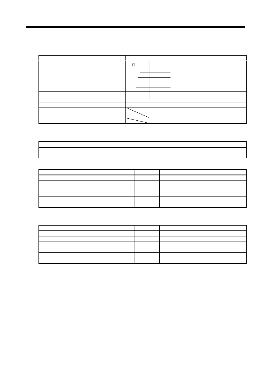
Perform home position return as required. Refer to Section 4.4 for home position return types. A
parameter setting example for dog type home position return is given here.
Parameter
Name
Setting
Description
No.8
Home position return type
000
Dog type home position return is selected.
Home position return is started in address
incremented direction.
Proximity dog (DOG) is valid at OFF.
No.9
Home position return speed
1000
Motion is made up to proximity dog at 1000r/min.
No.10
Creep speed
10
Motion is made up to home position at 10r/min.
No.11
Home position shift distance
0
No home position shift
No.42
Home position return position data
Used to set the current position on completion of home
position return.
No.43
Moving distance after proximity dog
Not used in dog type home position return.
After setting the above parameters, switch power off once. Then switch power on again to make the
set parameter values valid.
Create a program that executes a home position return. Here, create it as program No. 1.
Program
Description
ZRT
Zeroing
STOP
Program end
Set the input signals as listed below and switch on the forward rotation start (ST1) to execute
home position return.
Device name
Symbol
ON/OFF
Description
Automatic/manual selection
MD0
ON
Program operation mode is selected.
Program No. selection 1
DI0
OFF
Program No. selection 2
DI1
OFF
Program No.1 is selected.
Forward rotation stroke end
LSP
ON
CCW rotation side limit switch is turned on.
Reverse rotation stroke end
LSN
ON
CW rotation side limit switch is turned on.
Servo-on
SON
ON
Servo is switched on.
(g) Automatic operation
Set the input signals as listed below and switch on the forward rotation start (ST1) to execute
automatic operation in accordance with program No.2.
Device name
Symbol
ON/OFF
Description
Automatic/manual selection
MD0
ON
Automatic operation mode is selected.
Servo-on
SON
ON
Servo is switched on.
Forward rotation stroke end
LSP
ON
CCW rotation side limit switch is turned on.
Reverse rotation stroke end
LSN
ON
CW rotation side limit switch is turned on.
Program No. selection 1
DI0
ON
Program No. selection 2
DI1
OFF
Program No.2 is selected.
(h) Stop
In any of the following statuses, the servo amplifier interrupts and stops the operation of the servo
motor.
When the servo motor used is equipped with an electromagnetic brake, refer to Section 3.9 (3).
Note that forward rotation stroke end (LSP), reverse rotation stroke end (LSN) off has the same
stopping pattern as described below.
1) Servo-on (SON) OFF
The base circuit is shut off and the servo motor coasts.
2) Alarm occurrence
When an alarm occurs, the base circuit is shut off and the dynamic brake is operated to bring the
servo motor to a sudden stop.
3) Forced stop (EMG) OFF
The base circuit is shut off and the dynamic brake is operated to bring the servo motor to a
sudden stop. Servo forced warning (A.E6) occurs.
4) Forward rotation stroke end (LSP), reverse rotation stroke end (LSN) OFF
The droop pulse value is erased and the servo motor is stopped and servo-locked. It can be run in
the opposite direction.