Signals and wiring – MITSUBISHI ELECTRIC MR-J2S- CL User Manual
Page 68
3 - 21
3. SIGNALS AND WIRING
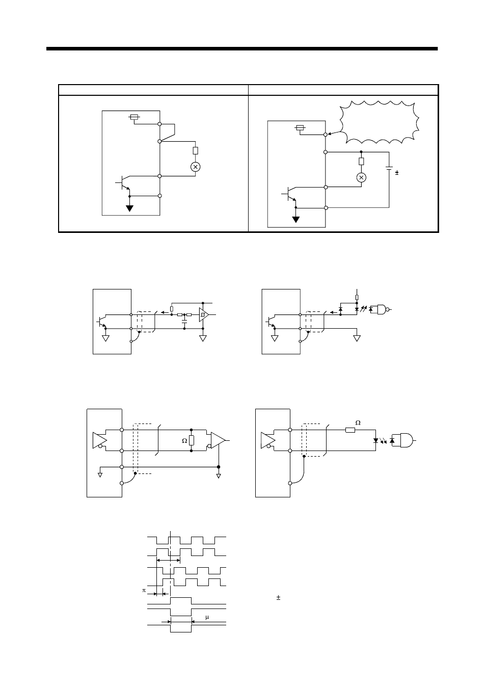
(b) Lamp load
For use of internal power supply
For use of external power supply
24VDC
VDD
COM
R
Servo amplifier
ALM, etc.
SG
COM
SG
R
24VDC
10%
Servo amplifier
ALM, etc.
VDD
24VDC
Do not connect
VDD-COM.
(3) Encoder pulse output DO-2
(a) Open collector system
Interface
Servo amplifier
OP
5 to 24VDC
Photocoupler
SD
Max. output current : 35mA
LG
Servo amplifier
OP
SD
LG
(b) Differential line driver system
1) Interface
Max. output current: 35mA
LA
(LB, LZ)
LAR
(LBR, LZR)
LG
SD
LA
(LB, LZ)
LAR
(LBR, LZR)
SD
Servo amplifier
Servo amplifier
Am26LS32 or equivalent
High-speed photocoupler
150
100
2) Output pulse
Servo motor CCW rotation
LA
LAR
LB
LBR
LZ
LZR
T
/2
400 s or more
OP
LZ signal varies 3/8T on its leading edge.