Parameters – MITSUBISHI ELECTRIC MR-J2S- CL User Manual
Page 152
5 - 19
5. PARAMETERS
Class No. Symbol
Name and Function
Initial
value
Unit
Setting
range
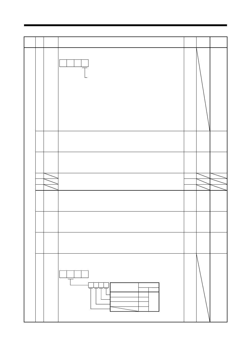
68
*CDP Gain changing selection
Used to select the gain changing condition. (Refer to Section 9.3)
0
0 0
Gain changing selection
Gains are changed in accordance with the settings
of parameters No. 64 to 67 under any of the following
conditions:
0: Invalid
1: Gain changing (CDP) signal is ON
2: Command frequency is equal to higher than
parameter No. 69 setting
3: Droop pulse value is equal to higher than
parameter No. 69 setting
4: Servo motor speed is equal to higher than
parameter No. 69 setting
0000
Refer to
Name
and
function
column.
69
CDS
Gain changing condition
Used to set the value of gain changing condition (command frequency, droop
pulses, servo motor speed) selected in parameter No. 68. The set value unit
changes with the changing condition item. (Refer to Section 9.5)
10
kpps
pulse
r/min
10 to
9999
70
CDT
Gain changing time constant
Used to set the time constant at which the gains will change in response to the
conditions set in parameters No. 68 and 69.
(Refer to Section 9.5)
1
ms
0 to 100
71
10
72
10000
73
For manufacturer setting
Don’t change this value by any means.
10
74
OUT1 OUT1 output time setting
Used to set the output time of OUT1. The OUT1 is turned on by OUTON
program command.
If "0" is set, it keeps ON.
0
10ms 0 to 2000
75
OUT2 OUT2 output time setting
Used to set the output time of OUT2. The OUT2 is turned on by OUTON
program command.
If "0" is set, it keeps ON.
0
10ms 0 to 2000
76
OUT3 OUT3 output time setting
Used to set the output time of OUT3. The OUT3 is turned on by OUTON
program command.
If "0" is set, it keeps ON.
0
10ms 0 to 2000
Ex
pan
si
on
par
ame
te
rs
2
77
*SYC1 Program input polarity selection 1
Used to select the device that reverses the input polarity of Program input 1
(PI1), Program input 2 (PI2), Program input 3 (PI3).
BIN 0 : Positive logic
Signal name
0
0
0
0
Initial value
BIN
HEX
Program input 1
Program input 2
Program input 3
0
0
0
0
BIN 1 : Negative logic
0000
0000h
to
FFFFh