GarrettCom 6K32 User Manual
Page 38
Magnum 6K32 Managed Switch Installation and User Guide (02/05)
32
www GarrettCom com
.
.
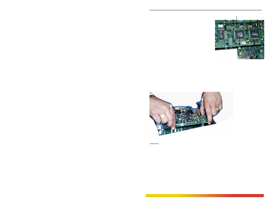
Step 2. Remove retaining screws placed on top for the 6KPM and Face Plate
On the top of the daughter module there are six
retaining screws for each 6KPM card. These
screws are used to secure a 6KPM card in
position (see Figure 3.5.3a). Remove the three
standoffs holding the Granddaughter board with
the chassis. The screen faceplate screws out from
the inside front of the chassis cover by loosening
the 4 screws and bracket while holding it down
firmly. Figure 3.5.3a: Top View
- 6 retaining screws shown by arrows
Step 3. Remove 6KPM Card
Carefully and gently pull out the daughter board from the latching connectors, using both
hands, gripping the board near the latch-up connectors as shown in Fig. 3.5.3b . If the
now empty slot is to remain unused, be sure to install a 6KPM-BLNK face plate cover.
Figure 3.5.3b:
Removing a
6KPM Card
Follow the step 8 to complete the process successfully.
NOTE:1. If the modular slot has not being used and moved to other unit, the empty
slot must be covered with Blank cover, to maintain proper air-inflow inside the unit
and keep off from dust and other unavoidable substance, otherwise can cause a failure
in the Switch.
2. If the PM module in the modular slot is not being installed properly or loose in
connection, the MNS-6K management software will not boot-up properly and a error
will generate as –{ failed to read register device type (offset 0x1600) on slot “A or B or
C or D”}, whichever the slot has been used.
3. Always boot-up the Switch after any new module installation on modular slot to
confirm the successful installation, before placing the chassis cover.