GarrettCom 6K32 User Manual
Page 34
Magnum 6K32 Managed Switch Installation and User Guide (02/05)
28
www GarrettCom com
.
.
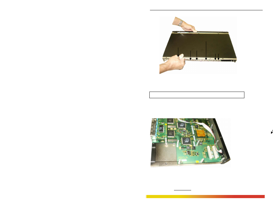
Fig 3.5.1b: Pulling out the top coved from the chassis base
Caution: Be careful not to disturb the power supply.
Looking down into the Magnum 6K32 unit, notice that there are individual PM
installation spaces and female latch (white) connectors provided on the far right side of
main board along with four stand-off’s for 6KPM card position. (See Figure 3.5.1c).
Figure 3.5.1c:
Magnum 6K32’s
modular slot side
(front-right side),
without chassis
cover
Step 3. Remove front panel face plate retaining screws
There are one PM slot located on the front-right side of the chassis cover. Looking into
the vertical placed Chassis cover of the unit, there are one bracket with retaining screws