GarrettCom 6K32 User Manual
Page 33
Magnum 6K32 Managed Switch Installation and User Guide (02/05)
27
www GarrettCom com
.
.
Caution- Avoid Static Discharge: The port modules (like most electronic
equipment) are sensitive to static discharge. Use proper ESD measures
when handling port modules.
Step 1. Make sure the 6KPM Card package has all necessary accessories to install it
properly. Each 6KPM Card package, for field installation contains
(Daughterboard (Bigger) and Granddaughter board (smaller), three 5/8 stand
offs for Granddaughter board, six #4-40 Pan-Head screws along with Front
panel face plate package. The Front panel faceplate package includes 3 retainer
brackets and six #2-56 flat head screws.
NOTE: Every 6KPM Card package comes with their matching Daughter and
Granddaughter board. The copper 6KPM card should not work properly if
mixed with other Fiber combo 6KPM card packages. Always install the PM
module separately one by one to avoid the mixing.
Step 2. Remove Chassis Cover
The Magnum 6K32 chassis are combined with top, bottom and front panel
parts and assembled together with the help of 17 Philips-head screws. There are
5 screws located on the front-bottom and 3 at rear-top of the unit and one each
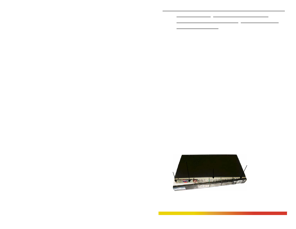
on the front and rear sides. First Remove the front panel screws (total 12) as
shown in the fig 3.5.1a after the remove. Once these are removed, the front
panel can be easily pulled out to the front. The top cover can be easily pulled
off to the front from the chassis base, as shown in the Fig. 3.4.1b. When the
chassis top cover has been removed, the interior of the unit is exposed.
Figure 3.5.1a: Removing front panel after the screws being removed