Blade elevation gauge, Adjusting the support wheel – Grizzly G0503 User Manual
Page 45
Model G0503 (Mfg. Since 12/08)
-43-
Blade Elevation
Gauge
figure 25. Blade guide upper plate.
Blade Elevation
pointer
Tools Needed
Qty
wrench/socket 17mm ....................................... 1
Calipers ............................................................. 1
To adjust the blade elevation gauge:
1. adjust the blade height until the blade eleva-
tion gauge reads
1
⁄
2
".
2. run a test piece through the resaw and
measure the thickness of the test piece with
calipers.
3. Disconnect the resaw from power!
4. loosen the bolt holding the blade elevation
pointer and adjust the pointer until it is set at
the same thickness as the test piece.
5. tighten the blade elevation pointer bolt and
run another test piece through the resaw to
confirm the elevation pointer setting.
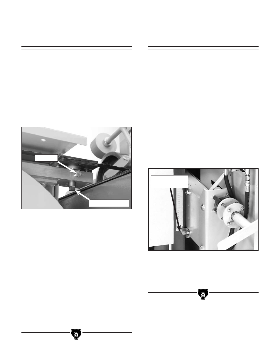
figure 58. support wheel components.
2. rotate the adjustment shaft until the support
wheel is approximately 0.016" behind the
back of the blade. Check with a feeler gauge
or four thicknesses of a dollar bill.
3. tighten the lock bolt.
4. spin the wheels clockwise by hand. if the
support wheels turn, increase the spacing
between the blade and the bearing (the
bearings should only turn when cutting).
note—to prevent the blade from wearing a
groove into the support wheel adjust the height
periodically. Move the adjustment shaft up or
down until the blade contacts the support wheel
in a new place.
adjustment shaft
lock Bolt
Adjusting the
Support Wheel
the support wheel is positioned behind the blade
to brace it from pushing backwards during a cut.
Check the support wheel spacing each time a
new blade is installed.
Tools Needed
Qty
wrench/socket 17mm ...................................... 1
To adjust the support wheel:
1. loosen the lock bolt shown in figure 58.