Grizzly G0503 User Manual
Page 43
Model G0503 (Mfg. Since 12/08)
-41-
figure 54. straightedge placement.
figure 55. Correct alignment.
7. Tilting forward—to move the top of the
wheel forward, loosen the lock bolt and tight-
en the neighboring adjustment bolt. always
loosen the jam nuts before moving the
adjustment bolts, and always tighten the jam
nuts after moving the adjustment bolts.
Tilting Backward—to move the top of the
wheel backward, loosen the adjustment bolt,
then tighten the neighboring lock bolt.
8. place the straightedge across the wheels, as
shown in
figure 54, and examine how the
wheels line up with each other.
—if the straightedge lies flat across the sur-
face of both wheels as shown in
figure
55, skip to step 11.
—if the wheels are not aligned, determine
which direction they need to move in order
to be correct, then proceed to
step 9.
9. loosen the jam nuts on the tracking adjust-
ing bolts and loosen the lock bolts. (see
figure 56)
5. Move the bars to the other side of the con-
veyor belt and check the adjustable wheel.
—if the wheels have the same angle com-
pared to the conveyor table, go to
step 8.
—if the wheels have different angles, pro-
ceed to
step 6.
6. loosen the lock bolts and the jam nuts on
the vertical adjusting bolts at the top of the
adjusting plate shown in
figure 54.
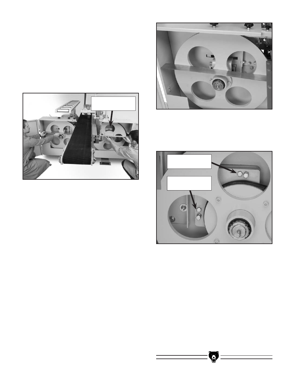
figure 56. tracking adjustment bolts.
10. adjust the wheels until the wheel position is
correct when checked with the straightedge.
11. spin the wheels by hand to check tracking.
12. Fine tune the adjustment bolts until the blade
tracks correctly.
13. adjust the guide bearings, close the wheel
cover, and connect the machine to the power
source to prepare the saw for a test run.
14. test run the resaw and repeat this entire
section if the blade does not track correctly.
Vertical
adjustment Bolts
tracking
adjustment Bolts
Vertical
adjustment Bolts