Port assignment of the connection blades, 10 port assignment of the connection blades, 118 operating manual – FUJITSU BX900 S1 User Manual
Page 118: Hot-plug components, Bx900 s1
118
Operating Manual
BX900 S1
Hot-plug components
©
c
o
g
n
it
as
. Ges
e
lls
c
h
ft
f
ü
r
T
e
c
hni
k
-D
o
k
u
m
e
nt
at
ion m
b
H 20
10
P
fa
d
:
C
:\
P
rogra
m
m
e
\F
C
T
\t
im
_a
pp
\t
im
_l
o
c
a
l\
w
or
k
\W
A
LT
E
R
\O
B
J
_
D
O
K
U
-4
9
5
3
-0
06
.f
m
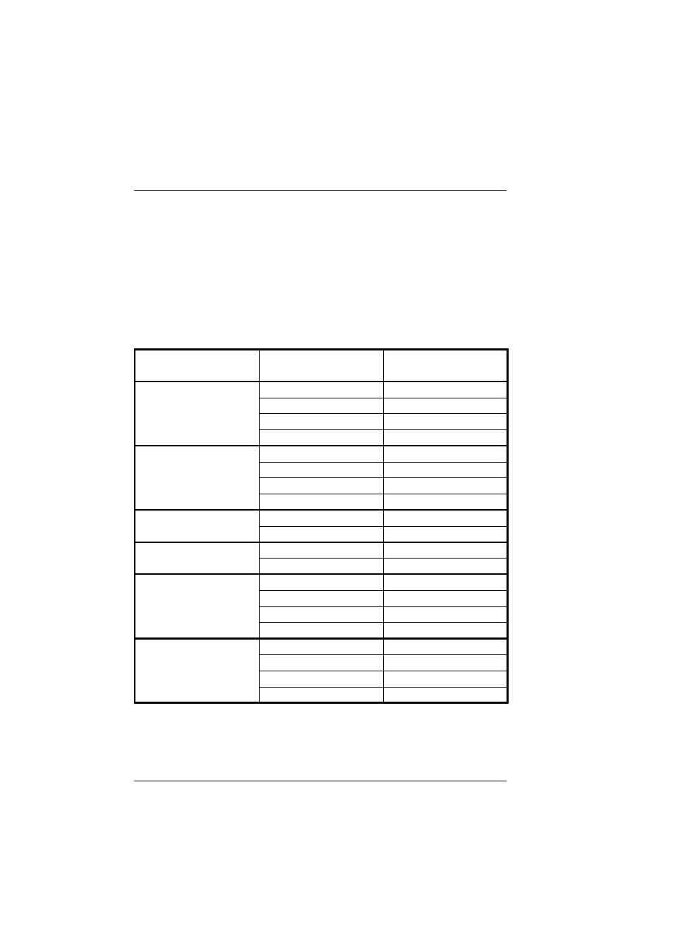
8.2.10 Port assignment of the connection blades
The A-channels of the controllers in the server blades are connected to the
connection blade slots on the left-hand side (CB1, CB3, CB5 and CB7). The B-
channels are connected to the slots on the right-hand side (CB2, CB4, CB6 and
CB8).
With the mezzanine cards, the assignment of the ports to the connection blade
slots can be defined via the management blade. The following figure shows the
different options.
mezzanine card
Mezzanine card slot (M)
Connection blade slot (CB)
Port (P)
Port (P)
FC 8Gb/s
M1.P0
CB3
M1.P1
CB4
M2.P0
CB5
M2.P1
CB6
LAN 1GbE
M1.P1 / M1.P3
CB3.P1 / CB3.P2
M1.P2 / M1.P4
CB4.P1 / CB4.P2
M2.P1 / M2.P3
CB7.P1 / CB7.P2
M2.P2 / M2.P4
CB8.P1 / CB8.P2
LAN 1GbE
M2.P1 / M2.P3
CB5.P1 / CB5.P2
Option 2
M2.P2 / M2.P4
CB6.P1 / CB6.P2
LAN 1GbE
M2.P1 / M2.P3
CB5.P1 / CB7.P2
Option 3
M2.P2 / M2.P4
CB6.P1 / CB8.P2
LAN 10GbE
M1.P1
CB3.P1
M1.P2
CB4.P1
M2.P1
CB5.P1
M2.P2
CB6.P1
Infiniband
M1.P1
---
M1.P2
CB3/CB4
M2.P1
CB7/CB8
M2.P2
CB5/CB6
Table 3: Port assignment of connection blades and mezzanine cards