HP XE3 User Manual
Page 70
2-42
Removal and Replacement
HP OmniBook XE3
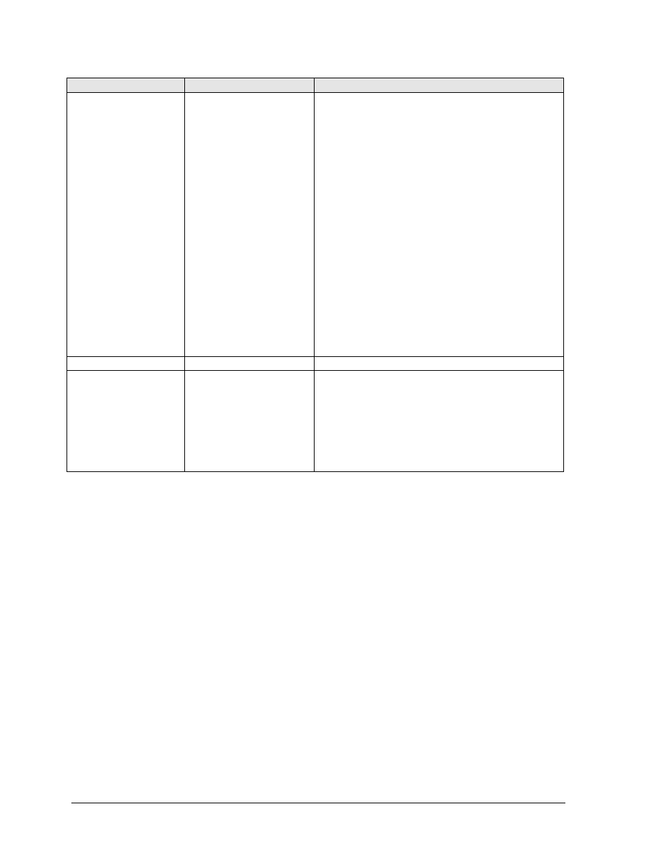
Component
Removal Procedure
Additional Steps
Plate, CPU support
Mini-PCI card (page 2-7).
Keyboard cover
(page 2-9).
Keyboard (page 2-11).
Hard disk drive assembly
(page 2-13).
Display assembly
(page 2-17).
Top case assembly
(page 2-19).
Hinge saddle set
(page 2-22).
Video PCA (page 2-25).
Heatsink assembly
(page 2-25).
CPU module (page 2-29).
Floppy disk drive assembly
(page 2-31).
CD-ROM/DVD drive
(page 2-33).
Motherboard (page 2-34).
Saddle, hinge set
See page 2-22.
Socket, PCMCIA
Keyboard cover
(page 2-9).
Keyboard (page 2-11).
Display assembly
(page 2-17).
Top case (page 2-19).
Hinge saddle set
(page 2-22).
Remove the four screws attaching the PCMCIA socket
to the motherboard (M2.5x4), and remove the socket.
See also other documents in the category HP Notebooks:
- EliteBook 8440p (169 pages)
- XZ100 (104 pages)
- ZT1100 (58 pages)
- 110 (104 pages)
- ze2000 (213 pages)
- OmniBook 2000 Notebook PC (70 pages)
- 1103 (101 pages)
- ze4200 (126 pages)
- TC1 100 (17 pages)
- 15 (101 pages)
- XB4000 (43 pages)
- ze2300 (239 pages)
- Laptop Docking Station (70 pages)
- VXI E1432A (222 pages)
- V6115TU (22 pages)
- 210 (67 pages)
- zt3000 (186 pages)
- XB3000 (79 pages)
- xe310 (12 pages)
- COMPAQ TC4400 (219 pages)
- 367055-002 (26 pages)
- Compaq Tablet PC TC1 100 (23 pages)
- 463777-001 (42 pages)
- zx5000 (272 pages)
- VC133 (38 pages)
- USB Media Docking Station VY847AA#ABA (1 page)
- ze4100 (5 pages)
- 2000 (118 pages)
- ZE4900 (182 pages)
- V4200 (273 pages)
- Compaq Tablet PC TC1100HP (22 pages)
- EliteBook 6930p Notebook PC (35 pages)
- Chromebook 11 G2 (23 pages)
- EliteBook Folio 9470M-Notebook-PC (33 pages)
- EliteBook 2570p Notebook PC (107 pages)
- EliteBook 2570p Notebook PC (106 pages)
- ProBook 6470b Notebook-PC (126 pages)
- ProBook 6470b Notebook-PC (113 pages)
- EliteBook 2540p Notebook PC (175 pages)
- EliteBook 2540p Notebook PC (173 pages)
- EliteBook 2540p Notebook PC (177 pages)
- EliteBook 2540p Notebook PC (23 pages)
- ProBook 6460B Notebook-PC (45 pages)
- mt41 Mobile Thin Client (90 pages)