Disassembly flowchart – HP XE3 User Manual
Page 30
2-2
Removal and Replacement
HP OmniBook XE3
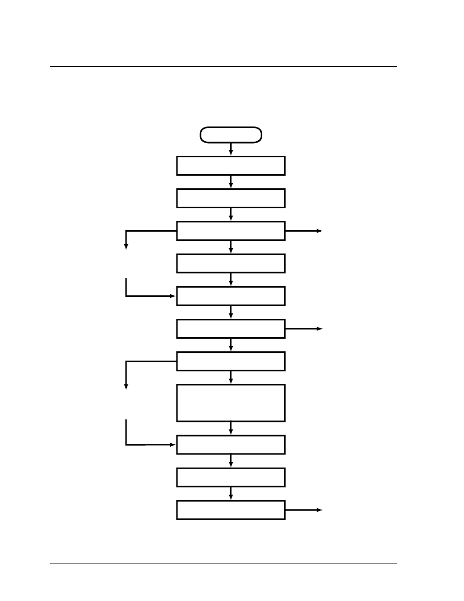
Disassembly Flowchart
The following diagram shows the general “path” you will use in disassembling the notebook to access
any particular component.
Figure 2-1. Disassembly Flow
Start
Battery, AC adapter,
SDRAM modules, mini-PCI card
Keyboard cover
Keyboard
Hard disk drive assembly
Display assembly
Top case assembly
Hinge saddle set
• CD-ROM/DVD drive assembly
• Video PCA
• Floppy disk drive assembly
• Headphone PCA
Heatsink assembly (with fan)
CPU module
Motherboard or
bottom case
CD player PCA
If removing only
heatsink assembly
or CPU module
Only if not removing
motherboard
or bottom case
Switchboard PCA
(also remove if removing
motherboard or bottom
case assembly)
• CPU support plate
• Docking doors
• PCMCIA doors
See also other documents in the category HP Notebooks:
- EliteBook 8440p (169 pages)
- ZT1100 (58 pages)
- XZ100 (104 pages)
- 110 (104 pages)
- ze2000 (213 pages)
- OmniBook 2000 Notebook PC (70 pages)
- 1103 (101 pages)
- ze4200 (126 pages)
- TC1 100 (17 pages)
- 15 (101 pages)
- XB4000 (43 pages)
- ze2300 (239 pages)
- Laptop Docking Station (70 pages)
- VXI E1432A (222 pages)
- V6115TU (22 pages)
- 210 (67 pages)
- zt3000 (186 pages)
- XB3000 (79 pages)
- xe310 (12 pages)
- COMPAQ TC4400 (219 pages)
- 367055-002 (26 pages)
- Compaq Tablet PC TC1 100 (23 pages)
- 463777-001 (42 pages)
- zx5000 (272 pages)
- VC133 (38 pages)
- USB Media Docking Station VY847AA#ABA (1 page)
- ze4100 (5 pages)
- 2000 (118 pages)
- ZE4900 (182 pages)
- V4200 (273 pages)
- Compaq Tablet PC TC1100HP (22 pages)
- EliteBook 6930p Notebook PC (35 pages)
- Chromebook 11 G2 (23 pages)
- EliteBook 2570p Notebook PC (106 pages)
- EliteBook Folio 9470M-Notebook-PC (33 pages)
- EliteBook 2570p Notebook PC (107 pages)
- ProBook 6470b Notebook-PC (113 pages)
- ProBook 6470b Notebook-PC (126 pages)
- EliteBook 2540p Notebook PC (177 pages)
- EliteBook 2540p Notebook PC (23 pages)
- EliteBook 2540p Notebook PC (175 pages)
- EliteBook 2540p Notebook PC (173 pages)
- ProBook 6460B Notebook-PC (45 pages)
- mt41 Mobile Thin Client (90 pages)