AERCO RECON 1000 User Manual
Page 90
RECON Water Heaters Installation, Operation & Maintenance Manual
CHAPTER 6 – MAINTENANCE
Page 90 of 178
AERCO International, Inc.
100 Oritani Dr. Blauvelt, NY 10913
OMM-0103_0A
PRI: 10/28/2014
Phone: 800-526-0288
GF-147
6.8.1 Pumping System Set-Up
A sample pumping set-up diagram is shown in Figure 6-9 A and 6-9 B. As this diagram shows,
heat exchanger cleaning is accomplished by pumping the HydroSkrub solution from a large
circulation bucket to the heat exchanger drain valve, through the heat exchanger and then out
through the output connection of the heater. Set up the pumping system as follows:
Pumping System Set-Up Instructions
1. Turn off the water heater and close the inlet and outlet isolation valves.
2. Open the drain valve (see Figure 6-9 B) and drain at least half of the heat exchanger water-
side volume. When full, RECON models hold approximately the following gallons of water:
RECON500: 27 gallons
RECON1000: 25 gallons
NOTE: The volume of water drained must equal the volume of HydroSkrub added.
3. Route the test hose bib (see section 2.6, above,) ball valve and hose connection from the hot
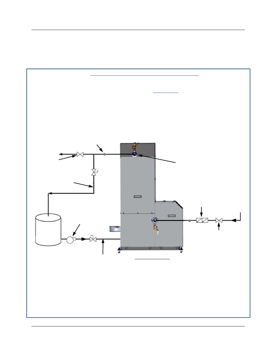
water outlet piping to the top of a suitably sized circulation bucket (see Figure 6-9 A).
Figure 6-9 A: Sample Heat Exchanger Cleaning Set-Up
4. Close the hot water outlet and cold water inlet valves.
5. Connect a pump from the circulation bucket to the drain valve (see Figure 6-9 B).
TEST HOSE BIB
CONNECTION
UNION
BACK-FLOW
PREVENTOR
CLOSE COLD
WATER INLET
VALVE
COLD
WATER
IN
PUMP
CIRCULATION
BUCKET
HOT WATER OUTLET
CONNECTION
CONNECT TO DRAIN
VALVE ON RIGHT SIDE,
SEE FIGURE 6-9 B
LEFT SIDE VIEW
HOT WATER
OUTLET VALVE