AERCO RECON 1000 User Manual
Page 26
RECON Water Heaters Installation, Operation & Maintenance Manual
CHAPTER 2 – INSTALLATION
Page 26 of 178
AERCO International, Inc.
100 Oritani Dr. Blauvelt, NY 10913
OMM-0103_0A
PRI: 10/28/2014
Phone: 800-526-0288
GF-147
2.9 CONDENSATE DRAIN & PIPING
The RECON Water Heater is designed to condense water vapor from the flue products.
Therefore, the installation must have provisions for suitable condensate drainage or collection.
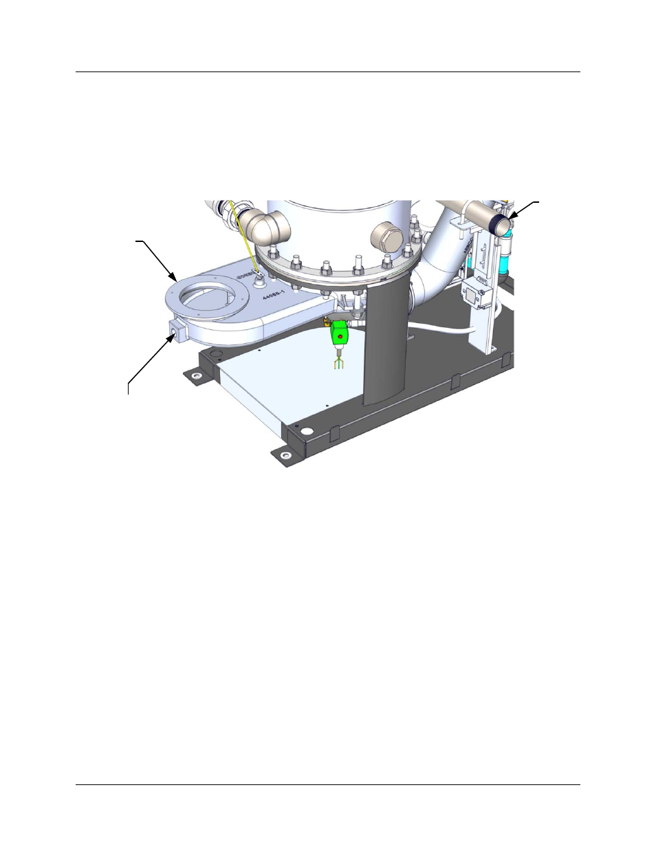
The condensate drain port is located on the exhaust manifold at the rear of the unit (Figure 2-8).
This drain port must be connected to the Condensate Trap (part no. 24060) which is packed
separately within the unit’s shipping container. The Condensate Trap inlet and outlet
connections contain tapped 3/4” NPT ports.
Figure 2-8: Condensate Drain Connection Location – Left-Rear View
A sample Condensate Trap installation is shown in Figure 2-9. However, the actual installation
details for the trap will vary depending on the available clearances, housekeeping pad height/
dimensions and other prevailing conditions at the site. The following general guidelines must be
observed to ensure proper condensate drainage:
The condensate trap inlet (Figure 2-9) must be level with, or lower than the exhaust
manifold drain port.
The base of the condensate trap must be supported to ensure that it is level (horizontal).
The trap must be removable for routine maintenance. AERCO recommends that a union
be utilized between the exhaust manifold condensate drain port and the trap inlet port.
While observing the above guidelines, install the condensate trap as directed in the following
instructions:
COLD
WATER
INLET
(2” NPT)
EXHAUST
MANIFOLD
CONDENSATE DRAIN
CONNECTION
(3/4” NPT)