AERCO RECON 1000 User Manual
Page 61
RECON Water Heaters Installation, Operation & Maintenance Manual
CHAPTER 4 – INITIAL START-UP
OMM-0103_0A
AERCO International, Inc.
100 Oritani Dr. Blauvelt, NY 10913
Page 61 of 178
GF-147
Phone: 800-526-0288 PRI:
10/28/2014
NATURAL GAS Combustion Calibration – Continued
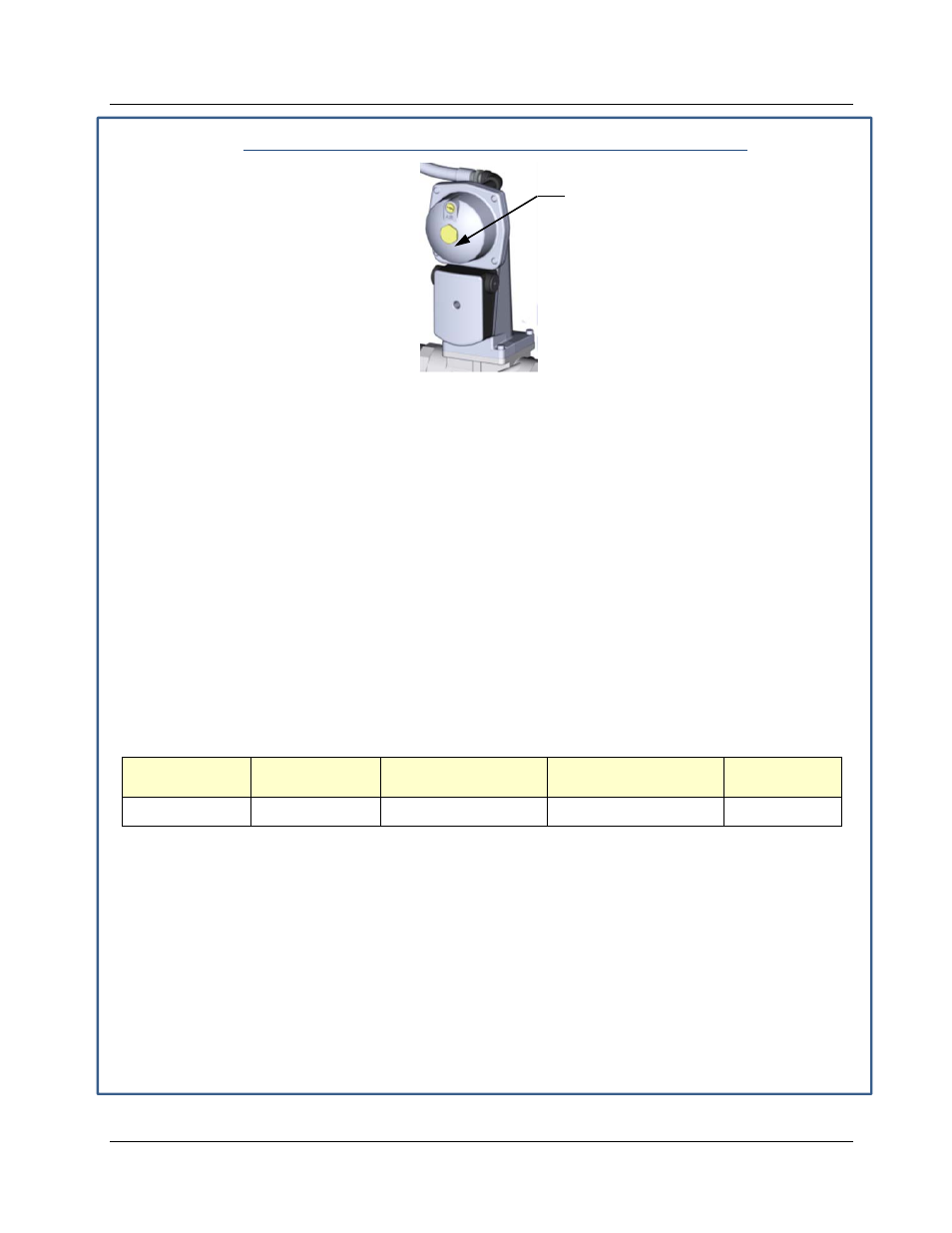
Figure 4-4: Gas Pressure Adjustment Screw Location
13. Replace the brass cap on the SSOV gas pressure adjustment if it was previously removed.
14. With the valve position at 100%, insert the combustion analyzer probe into the flue probe
opening and allow enough time for the combustion analyzer reading to stabilize.
15. Compare the oxygen (O
2
)
level, carbon monoxide (CO), nitrogen oxide (NOx) and flame
strength readings with the range
shown in step 19, below. You may need to adjust O
2
% above
this range to meet ultra-low NOx requirements or to avoid combustion tone issues.
16. Press the MENU key on the front panel of the C-More until Combustion Cal Menu appears
on the display.
17. Press the ▲ arrow key until SET Valve Position reads 100%. Press the ENTER key.
18. Press the CHANGE key and observe that CAL Voltage 100% is flashing.
19. The oxygen level at the 100% valve position should be as shown below. Also, ensure that the
nitrogen oxide (NOx), carbon monoxide (CO) and flame strength readings match the following
values:
Combustion Calibration Readings
at 100% Valve Position
Valve
Position
Oxygen (O
2
)
%
Nitrogen Oxide
(NOx)
Carbon Monoxide
(CO)
Flame µA
100%
6.0% ± 0.25%
<20 ppm
<100 ppm
> 6 µA
20. If the oxygen level is not within the specified range, adjust the level using the ▲ and ▼ arrow
keys. This will adjust the output voltage to the blower motor as indicated on the display.
Pressing the ▲ arrow key increases the oxygen level and pressing the down ▼ arrow key
decreases the oxygen level.
21. Once the oxygen level is within the specified range at 100%, press the ENTER key to store the
selected blower output voltage for the 100% valve position. Record all readings on the
Combustion Calibration Sheets provided.
22. Repeat steps 16 through 21 for the following valve positions (see NOTE below):
RECON 1000: 80%, 60%, 50%, 40%, 30%, 20%
RECON 500: 80%, 60%, 40%, 30%, 24%, 20%, 16%
BRASS HEX
HEAD CAP
(Remove to access gas
pressure adjustment screw)