Install the coupling guard – Goulds Pumps CV 3196 i-FRAME - IOM User Manual
Page 47
Install the coupling guard
WARNING:
• Never operate a pump without a properly installed coupling guard. Personal injury will occur if you
run the pump without a coupling guard.
• Always disconnect and lock out power to the driver before you perform any installation or
maintenance tasks. Failure to disconnect and lock out driver power will result in serious physical
injury.
• The coupling used in an Ex-classified environment must be properly certified and must be
constructed from a non-sparking material.
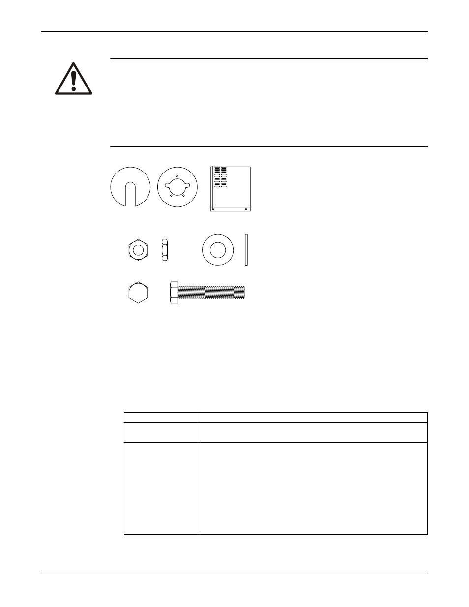
Required parts:
1
2
3
4
5
6
1.
End plate, drive end
2.
End plate, pump end
3.
Guard half, 2 required
4.
3/8-16 nut, 3 required
5.
3/8 in. washer
6.
3/8-16 x 2 in. hex head bolt, 3 required
1. De-energize the motor, place the motor in a locked-out position, and place a caution tag at the starter
that indicates the disconnect.
2. Put the pump-side end plate in place.
If the pump-side end plate is already in place, make any necessary coupling adjustments and then
proceed to the next step.
If the pump size is... Then...
STi, MTi, LTi
Align the pump-side end plate to the bearing frame. You do not need to
adjust the impeller.
XLT-i
1. Align the end plate on the pump side to the bearing housing so that
you meet these conditions:
a.
The large slots on the end plate do not touch the bearing housing
tap bolts.
b. The small slots align with the impeller adjusting bolts.
2. Fasten the end plate to the bearing housing using the jam nuts on the
impeller adjusting bolts.
3. Check the impeller clearance. Refer to the impeller clearance table for
the correct impeller clearance.
Commissioning, Startup, Operation, and Shutdown
Model CV 3196 i-FRAME Installation, Operation, and Maintenance Manual
45