Assembly references, Bolt torque values – Goulds Pumps CV 3196 i-FRAME - IOM User Manual
Page 123
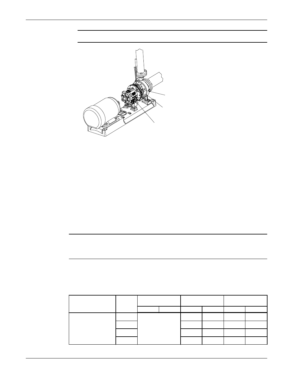
5. Install and tighten the casing jackscrews (418).
NOTICE: Do not overtighten the casing jackscrews. Doing so may result in equipment damage.
370F
370
108
6. Reinstall the shims under the frame foot and tighten the frame foot to the baseplate.
Make sure that you use the proper shim. Mount a dial indicator in order to measure the distance
between the top of the frame and the baseplate. Make sure that the distance does not change as you
tighten the frame-foot bolts.
7. Check the total clearance of the impeller in the casing.
With new parts, an acceptable range is 0.030 in. (0.76 mm) to 0.065 in. (1.65 mm). If the impeller
clearance is outside of this range, you either have the incorrect parts, an improper installation, or too
much pipe strain. Determine the cause and correct the problem before you proceed.
8. Adjust the impeller clearance.
Refer to the Impeller clearance setting section for more information.
9. Replace the auxiliary piping.
10. Fill the pump with the proper lubricant. See Lubricating-oil requirements.
11. Reinstall the coupling guard.
See Install the coupling guard for more information.
NOTICE:
Risk of damage to the mechanical seal or shaft sleeve on units supplied with cartridge mechanical seals.
Prior to startup, make sure to tighten the set screws in the seal locking ring and remove the centering clips.
Assembly references
Bolt torque values
This table provides the bolt torque values.
Table 18: Bolt torque, lb-ft (Nm)
Location
Frame
3196, CV 3196, LF
3196, 3796
NM 3196
3198
Lube
Dry
Lube
Dry
Lube
Dry
Casing bolts (370) or
casing nuts (425)
6-in. STi
Refer to the
maximum torque
values in lb-ft (Nm)
for casing bolts table.
27 (36)
40 (53)
N/A
N/A
8-in. STi
20 (27)
30 (40)
35 (47)
53 (71)
MTi, LTi
27 (36)
40 (53)
35 (47)
53 (71)
XLT-i, i17
N/A
N/A
N/A
N/A
Maintenance
Model CV 3196 i-FRAME Installation, Operation, and Maintenance Manual
121