Attach the i-alert™ condition monitor to the pump, Attach the i-alert, Condition monitor to the pump – Goulds Pumps CV 3196 i-FRAME - IOM User Manual
Page 120
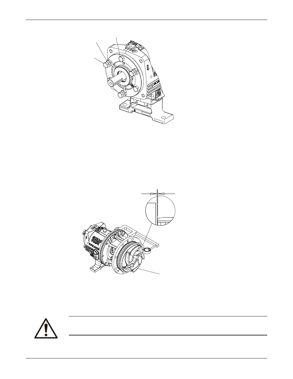
423
370D
370C
5. When you reach a 0.030 in. (0.76 mm) clearance, tighten the clamp bolts (370C), jack bolts (370D),
and lock nuts (423).
This approximates the impeller position when it is set to 0.015 in. (0.38 mm) from the casing. Perform
a final impeller adjustment after you install the impeller into the casing.
6. Check the impeller (101) runout.
Check vane tip to vane tip. If the total indicator reading is greater than 0.005 in. (0.13 mm), determine
the cause and correct the issue before you proceed.
The CV 3196 impeller face is cast, not machined. You do not need to check the face runout.
.030
101
For more information on how to set the impeller clearances, refer to the Impeller-clearance checks and
Impeller-clearance setting sections in Commissioning, Startup, Operation, and Shutdown.
Attach the i-ALERT
™
Condition Monitor to the pump
CAUTION:
Always wear protective gloves. The pump and condition monitor can be hot.
Maintenance
118
Model CV 3196 i-FRAME Installation, Operation, and Maintenance Manual