C-face adapter – Goulds Pumps CV 3196 i-FRAME - IOM User Manual
Page 34
Perform complete alignment for a vertical correction
A unit is in complete alignment when both the angular indicator (A) and the parallel indicator (P) do not
vary by more than 0.002 in. (0.05 mm) as measured at four points 90° apart.
1. Set the angular and parallel dial indicators to zero at the top-center position (12 o’clock) of the driver
coupling half (Y).
2. Rotate the indicators to the bottom-center position (6 o’clock).
3. Record the indicator readings.
4. Make corrections according to the separate instructions for angular and parallel alignment until you
obtain the permitted reading values.
Perform complete alignment for a horizontal correction
A unit is in complete alignment when both the angular indicator (A) and the parallel indicator (P) do not
vary by more than 0.002 in. (0.05 mm) as measured at four points 90° apart.
1. Set the angular and parallel dial indicators to zero at the left side of the driver coupling half (Y), 90°
from the top-center position (9 o’clock).
2. Rotate the indicators through the top-center position to the right side, 180° from the start position
(3 o’clock).
3. Record the indicator readings.
4. Make corrections according to the separate instructions for angular and parallel alignment until you
obtain the permitted reading values.
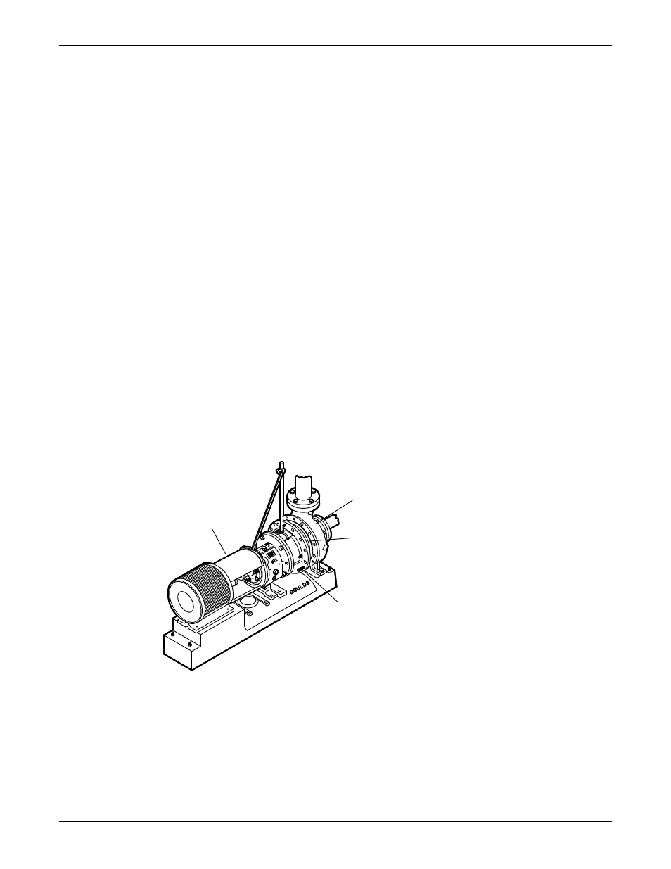
C-face adapter
Intended use
The C-face adapter is a device that attaches the pump to the drive unit to minimize the axial and radial play
between the two coupling halves.
Illustration
340
100
351
418
Figure 15: Example of the C-face adapter (340)
Alignment requirements
When you use a C-face adapter, you do not have to align the shaft. The rabbeted fittings of the drive unit
to the adapter and the adapter to the bearing frame automatically align the shaft to within the specified
limits.
Installation
32
Model CV 3196 i-FRAME Installation, Operation, and Maintenance Manual