12 bottom panel switch and connectors, 1 at/atx mode selection, 2 lan connection – IEI Integration UPC-12AH_GM45 v1.00 User Manual
Page 68
UPC-12A/GM45 Panel PC
Page 56
4.12 Bottom Panel Switch and Connectors
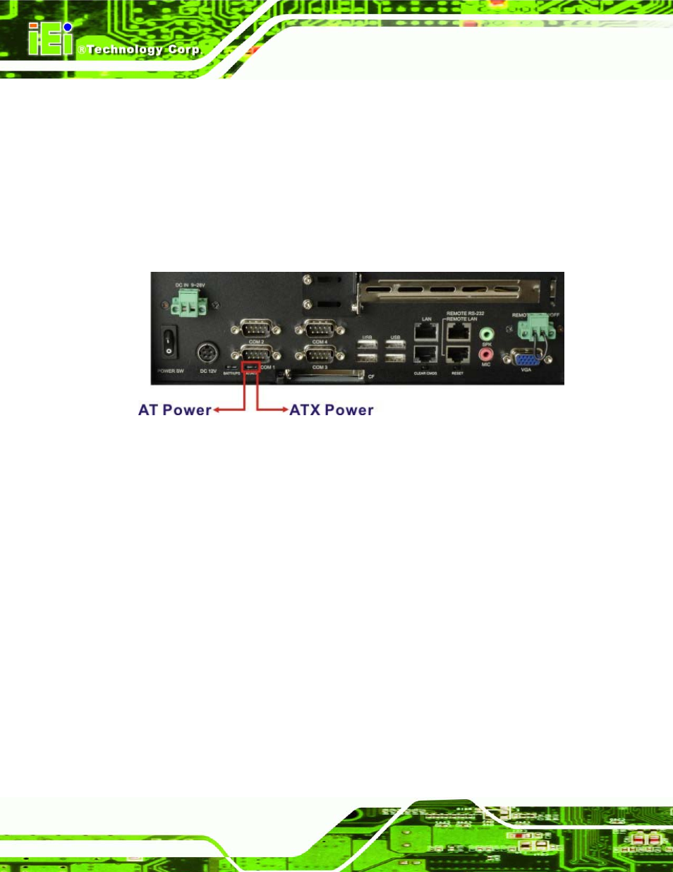
4.12.1 AT/ATX Mode Selection
AT and ATX power modes can both be used on the EP series panel PC. The selection is
made through an AT/ATX switch on the chassis rear panel (
568H568H
Figure 4-23
). To select AT
mode or ATX mode, follow the steps below.
Step 1:
Locate the AT/ATX switch on the chassis rear panel (
569H569H
Figure 4-23
).
Figure 4-23: AT/ATX Switch
Step 2:
Adjust the AT/ATX switch. The default mode is ATX mode (
570H570H
Figure 4-23
).
Step 0:
4.12.2 LAN Connection
There is one external RJ-45 LAN connector. The RJ-45 connector enables connection to
an external network. To connect a LAN cable with an RJ-45 connector, please follow the
instructions below.
Step 1:
Locate the RJ-45 connectors
on the I/O interface panel of the UPC-12A/GM45
series.
Step 2:
Align the connectors.
Align the RJ-45 connector on the LAN cable with one of
the RJ-45 connectors on the I/O interface panel of the UPC-12A/GM45 series.
See
571H571H
Figure 4-24
.