IEI Integration UPC-12AH_GM45 v1.00 User Manual
Page 67
UPC-12A/GM45 Panel PC
Page 55
NOTE:
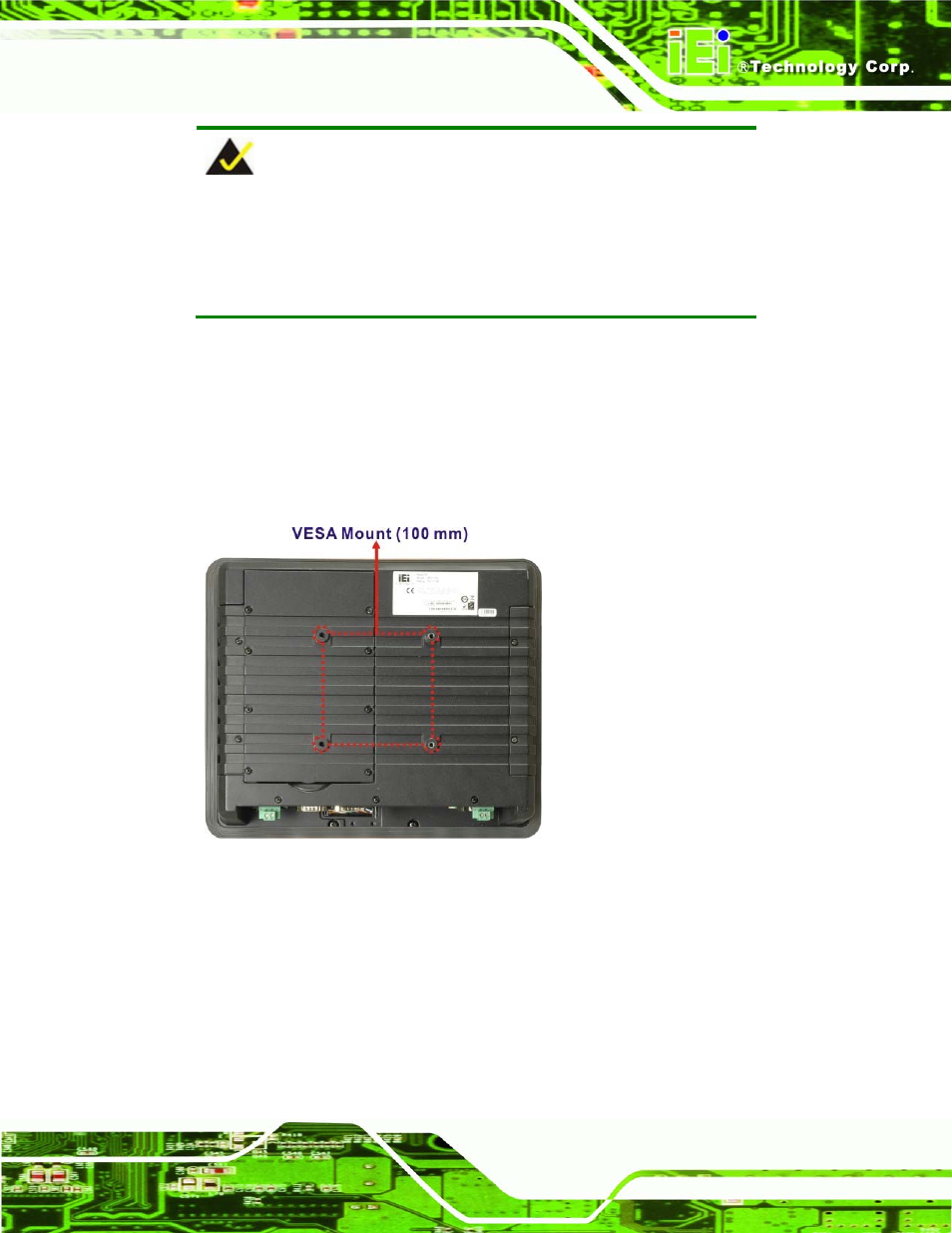
When purchasing the arm please ensure that it is VESA compliant and
that the arm has a 100 mm interface pad. If the mounting arm is not
VESA compliant it cannot be used to support the flat panel PC.
Step 2:
Once the mounting arm has been firmly attached to the surface, lift the flat panel
PC onto the interface pad of the mounting arm.
Step 3:
Align the retention screw holes on the mounting arm interface with those in the
flat panel PC. The flat panel PC arm mount retention screw holes are shown in
567H567H
Figure 4-22
.
Figure 4-22: Arm Mounting Retention Screw Holes
Step 4:
Secure the flat panel PC to the interface pad by inserting four retention screws
through the bottom of the mounting arm interface pad and into the
flat panel PC.
S
te
p
0
: