10 jumper settings – IEI Integration UPC-12AH_GM45 v1.00 User Manual
Page 54
UPC-12A/GM45 Panel PC
Page 42
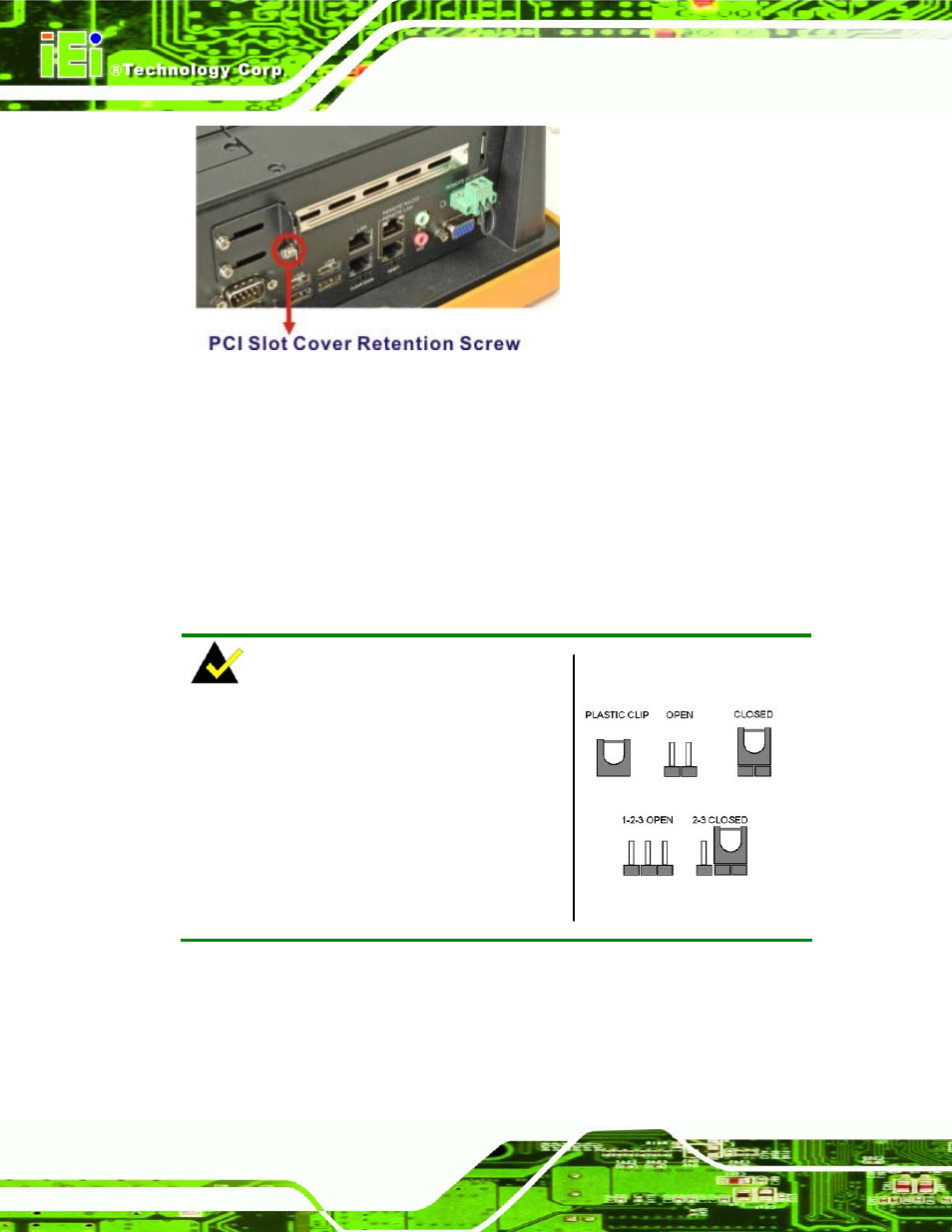
Figure 4-10: PCI Card Slot Cover Retention Screws
Step 3:
Insert a PCI card into the PCI slot (
543H543H
Figure 4-10
).
Step 4:
Secure the PCI card with the retention screw (
544H544H
Figure 4-10
).
Step 5:
Replace the plastic back cover.
Step 0:
4.10 Jumper Settings
NOTE:
A jumper is a metal bridge used to close an
electrical circuit. It consists of two or three metal
pins and a small metal clip (often protected by a
plastic cover) that slides over the pins to connect
them. To CLOSE/SHORT a jumper means
connecting the pins of the jumper with the plastic
clip and to OPEN a jumper means removing the
plastic clip from a jumper.
Figure 4-11: Jumper Locations
The following jumpers can be found on the motherboard installed in the UPC-12A/GM45.
Before the UPC-12A/GM45 is installed, the jumpers must be set in accordance with the
desired configuration. The jumpers on the UPC-12A/GM45 motherboard are listed in
545H545H
Table 4-1
.