Appliance setup – Heat & Glo Fireplace Heat & Glo Fireplace 6000C User Manual
Page 61
Heat & Glo • 6000C, 6000C-IPI, 8000C, 8000C-IPI • 2164-900 Rev. T • 9/12
61
A. Remove Fixed Glass Assembly
See Section 14.H.
B. Remove the Shipping Materials
Remove shipping materials from inside or underneath the
firebox.
C. Clean the Appliance
Clean/vacuum any sawdust that may have accumulated
inside the firebox or underneath in the control cavity.
D. Accessories
Install approved accessories per instructions included
with accessories. Contact your dealer for a list of ap-
proved accessories.
WARNING! Risk of Fire and Electric Shock! Use ONLY
Hearth & Home Technologies-approved optional acces-
sories with this appliance. Using non-listed accessories
could result in a safety hazard and will void the warranty.
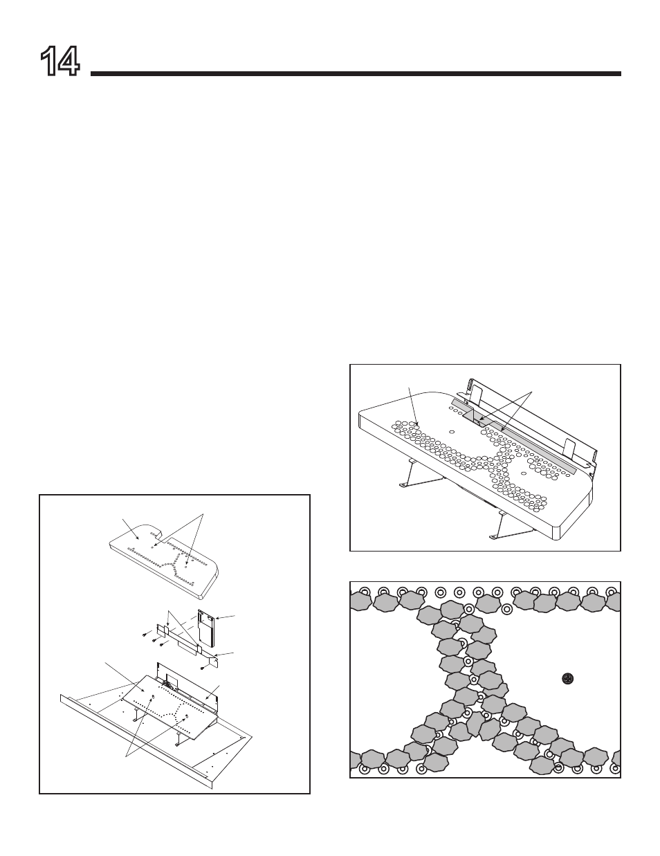
F. Ember Placement
WARNING! Risk of Explosion! Follow ember placement
instructions in manual. DO NOT completely block burner
ports with ember material. Replace ember material annu-
ally. Improperly placed embers interfere with proper burner
operation.
Ember material is shipped with this gas appliance. To place
the ember material:
• Embers CANNOT completely block burner ports. Care
should be taken not to block the lighting trail of ports.
• Embers may only be placed in areas as shown in Figure
14.2.
•
LP Only: Using dime-size pieces of Glowing Embers®,
overlap the burner ports (see Figure 14.3). The impingement
created by the embers will help blend the fire.
• Save the remaining ember materials for use during
appliance servicing. The embers provided should be
enough for 3 to 5 applications.
Figure 14.2 Placement of Embers
NO EMBERS IN SHADED AREAS
EMBERS
14
Appliance Setup
Figure 14.1
Figure 14.3 Embers Overlapping Burner Port Holes (LP only).
E. Burner Top Installation
1. Bend the two tabs upward as shown in Figure 14.1.
2. To install the fiber burner, mate the locating holes with
the guide sleeves. Install fiber burner top so that it
makes full contact with the underlying burner assem-
bly.
3. Ensure that the ports in the steel burner are visible
through the holes in the fiber burner top.
GUIDE SLEEVES
FIBER BURNER TOP
BURNER ASSEMBLY
PILOT COVER
LOCATING HOLES
BURNER SHIELD
AIR SCOOP
BEND TABS UP