System board overview – HP XU800 User Manual
Page 28
28
2 System Board
System Board Overview
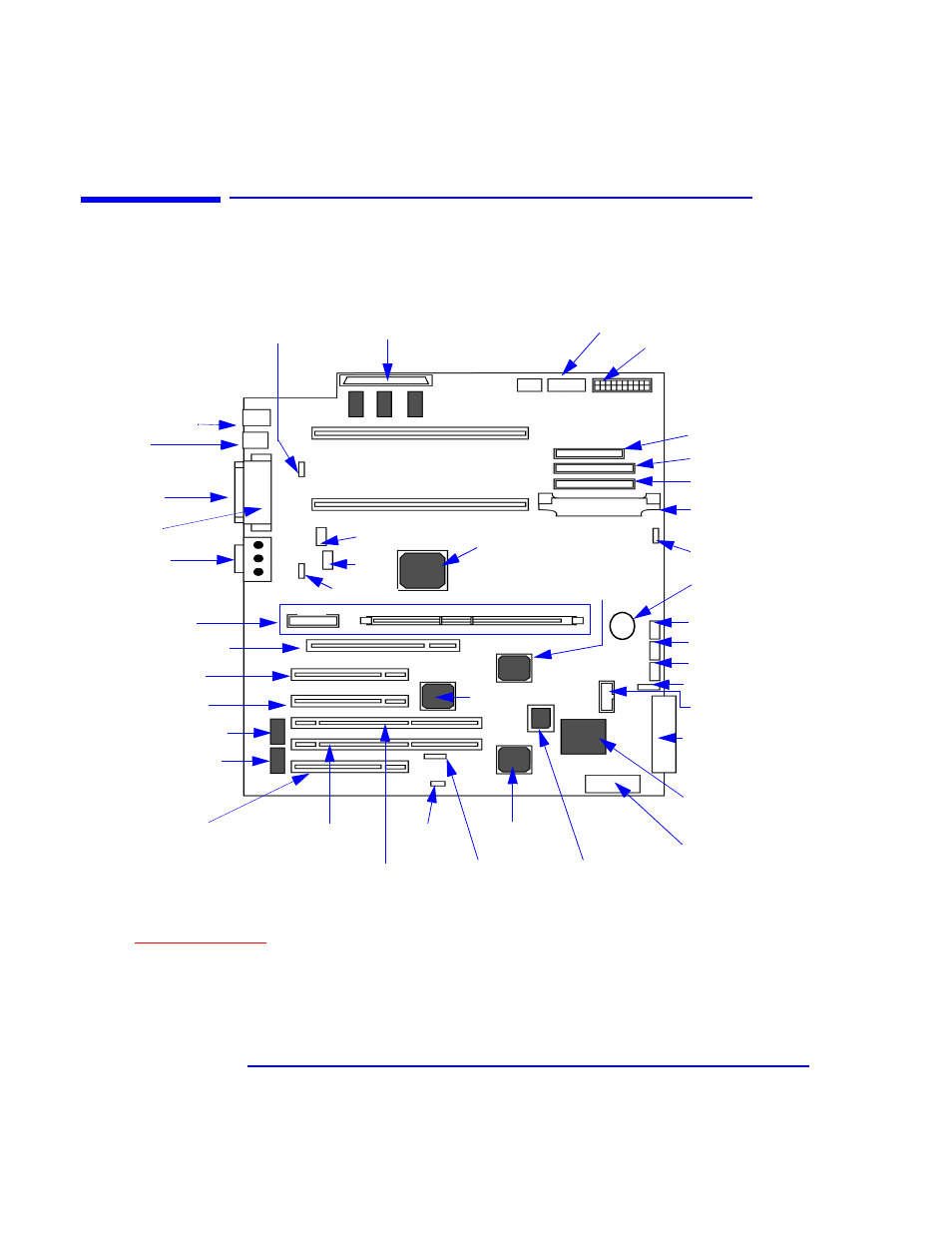
System Board Overview
The following diagram shows where the different chips and connectors are
located on the E-ATX system board.
PCI 64-bit Hub
(P64H)- U32
PCI Slot 1
(32-bit 33 MHz, 5V) - J15
Universal AGP PRO Slot - J22
PCI Slot 2
(32-bit 33 MHz, 5V) - J14
PCI Slot 5
(32-bit 33 MHz, 5V)- J11
PCI Slot 3 - J13
(64-bit 66 MHz, 3.3V)
PCI Slot 4 -J14
(64-bit 66 MHz, 3.3V)
Super I/O NS 87364 Chip - U6
CS4280 Audio PCI chip- U7
Additional SCSI
LED Connector -
J25
Wake-On Lan
c
(WOL)- J26
Configuration
Switches - SW1
a
a. Refer to
or the Switch Block Label located on the chassis of the system box for the different system board switch
settings.
AUX Audio In - J51
CD-ROM Audio In - J52
PCI Fan - J50
Status Panel - J43
Internal SCSI U160
Connector to Internal
Devices - J43
Adaptec 7892 SCSI
U160 Controller - U44
Battery - XU6
Input/Output Controller
Hub (ICH) 82801AA- U34
Memory Controller Hub
(MCH) 8284O-QP - U24
Battery - XU6
HDD Temperature
Sensor - J56
VRM for CPU 2 - J45
VRM socket for
CPU2 - J45
Primary IDE - J37
Secondary IDE - J44
FDD - J38
AUX Power- J31
Power Supply - J47
Processor 1 Connector - XU3
Processor 2 Connector - XU2
SCSI Termination
Connector - J23
Memory Expansion
Card Connectors- J22
Memory Expansion Card
Connectors - XU1, XU4
XU1
XU4
Anti-Intrusion
b
- J10
Fan CPU2
c
- J19
Rear Fan- J18
Midi & Audio - J2
Serial Port A - J5
Serial Port B - J4
(Both ports are stacked with
the Parallel Port)
Two USB - J8
Mouse (upper) &
Keyboard (lower) - J3
Fan CPU 1
c
- J17
MaxiLife -
U25
b. Connector for the Anti-Intrusion switch.
Line Out
Line In
MIC
c. Optional.
d. Connector for additional control of HDD LED on the status panel through the SCSI controller on a PCI add-on card.
FirmWare Hub
Controller (FWH)
82802AB- U35
Internal Speaker- J48