H" control board – Hoshizaki KM-151BAH User Manual
Page 16
11
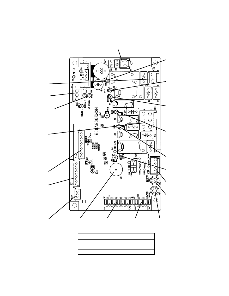
[a] CONTROL BOARD LAYOUT
"H" Control Board
Connector
K7
Transformer
Connector K3
Magnetic Contactor
Connector K4
Open
POWER OK LED
(Lights when power is
supplied to the board.
Flashes when bin control
is activated.)
Connector K5
Pins
#1 Fan Motor
#2 Hot Gas Valve
#3 Pump Motor
#4 Water Valve
#5 Open
#6 Drain Valve
Connector K6
Open
Connector K1
Pins
#1, 3 Float Switch
#2 Open
#4, 5 Bin Control
#6, 7 Thermistor
#8, 9 Open
Connector K2
Open
Alarm Buzzer S1 Dip Switch S2 Dip Switch
Alarm Reset Button
(service board only)
Relay LEDs (6)
(indicate which relays
are energized as
listed below)
LED 5 (X1 Relay)
Compressor (Comp)
Remote Fan Motor
(FMR)
LED 6 (X2 Relay)
Hot Gas Valve (HGV)
Self-Contained Fan
Motor (FMS) (FMS off
when LED on)
LED 8 (X4 Relay)
Inlet Water Valve (WV)
(Harvest Water Valve
(HWV) on units with
two inlet water valves)
LED 9 (X5 Relay)
Freeze Water Valve
(FWV) on units with
two inlet water valves
(service board only)
LED 4 (X6 Relay)
Drain Valve (DV)
LED 7 (X3 Relay)
Pump Motor (PM)
Connector K8
Open
Output Test Button
(used to test relays on
board)
Control Board
Part Number
P00013-03 (factory)
P00013-02 (service)
Type
HKM2006V003